Hello there!
|
Hey guys/girls,
Figured I'd do up a little introduction since I'm new here, and since I already foolishly posted a request (that had already been posted in the forum, and verified...) I'm still quite new to the whole pedal building thing, but this site has made the building process SO much easier! You guys are great, and I can't tell you how much I enjoy tackling your layouts with confidence. With layouts like these, my tired Canuck brain can try its hand at the enclosure finishing process... (another new endeavor!) So far, thanks to you, I've built: Fuzzhugger Phantom Octave Heartthrob Tremolo DBA Interstellar Overdriver and ZVex Fuzz Factory With plans to build many more. I started fairly recently, with the BYOC confidence boost, then migrated to Beavis Audio Research projects (I love the Noisy Cricket!) and have made my way here, hopefully a bit more experienced. Can't wait to build more! --Skajaquada |
|
Administrator
|
Welcome to the site, and glad you're enjoying it.

|
|
Thank you, sir!
One other thing I need to mention - that stickied post about parts sourcing is pretty damn awesome. That's been one of my major hurdles thus far, i.e. sourcing parts without losing my shirt in the process. I thought I reached a milestone when I found Tayda, but clearly, there's much more to learn. |
|
In reply to this post by Skajaquada
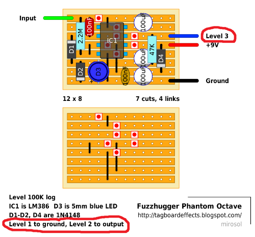
I'm also trying the phantom octave, but i'm wondering where you connected the output, since the only out labelled goes to the pot. How did you connect it to the switch?
|
|
In reply to this post by finnfuzz
I actually followed the offboard wiring from Beavis Audio Research, but yeah, what he said :)
|
|
Thanks for the reply. What seemed unique was that the only out went to the pot. When I linked the same strip to the switch, it worked but I wasn't sure if that was the idea. It looked like a circuit that 'bled' the signal to the pot, almost like a soak effect.
On Sat, May 17, 2014 at 2:45 PM, Skajaquada [via Guitar FX Layouts] <[hidden email]> wrote: I actually followed the offboard wiring from Beavis Audio Research, but yeah, what he said :) |
Maybe I'm misunderstanding you, but from your response, I'm guessing you wired it incorrectly. The output from the board goes to lug 3 of the Level pot. Lug 1 goes to ground, and lug 2 goes to the circuit output lug on the stomp switch (as described in the layout):  This way the Level pot is wired as a simple voltage divider. It is extremely common to have a volume pot wired this way as the last component in a circuit. When turned all the way counterclockwise, lug 2 is touching ground and there is no output. When turned all the way clockwise, lug 2 is touching the full signal applied to lug 3, and output is maximized. If you take the output from lug 3 of the Level pot (which is what happens when you link the output vero strip to the switch), you get maximum volume all the time, and turning the Level control does nothing at all. In that case, the pot is just acting as pulldown resistor. Forgive me if I've misinterpreted your statement. |
|
I'm guessing here, but I think the basic information you're looking for is:
Level lug two is the output, rather than the output being on the board. In this case, all you have to do is run a wire from lug two to where "board output" goes on the switch. Then run a wire from the "jack output" on the switch to the jack. Hope that answers your question. |
|
Sincere thanks. I was looking at a printout of the page, and it had cut off the last line of text. I kept looking for how it got back to the board, but I 'm seeing better now how the pot swings the whole board through itself. I'm getting closer. Just now checking my soldering and links. Thanks again for your patience and help.
On Mon, May 19, 2014 at 5:12 PM, Skajaquada [via Guitar FX Layouts] <[hidden email]> wrote: I'm guessing here, but I think the basic information you're looking for is: |
«
Return to Open Chat
|
1 view|%1 views
| Free forum by Nabble | Edit this page |

