Hotcake Bluesberry Mod
|
Hey there, I have been a long time lurker, first time poster. I am looking for any one with information on Thr Bluesberry mod for the Crowther Hotcake. I have built several and have had good success but a friend was wondering if I could add that feature to a combo box I am making for him. I understand it adds in a clipping diode but I am not sure where. Any help will be appreciated. Thanks for being a great resource.
|
|
You have built several Hotcakes and they worked?! I'm impressed!
 , I have to admit I'm a quitter, but after 2 attempts I thought: Next! :) , I have to admit I'm a quitter, but after 2 attempts I thought: Next! :)
I read John Kallas did it on his Hotcake.. Maybe He has an idea. I could only find this: The “Bluesberry” mod, which puts a 1N914 from pin 2 (cathode) to pin 3 of the IC, and from pin 2(cathode) to ground (pin 4). On this link: http://music.codydeschenes.com/?p=1948 How verified or true that is I can't tell from my experience unfortunately. And Welcome! :) |
|
Thanks for the response. I put a Cornish buffer in front of my Hotcake build, then tweaked them to match my actual Crowther Hotcake. I like putting them in boxes with other effects like the EQD Speaker Cranker.
Now, when they say cathode, I assume they mean of the diode? |
|
This post was updated on .
In reply to this post by Thorquil
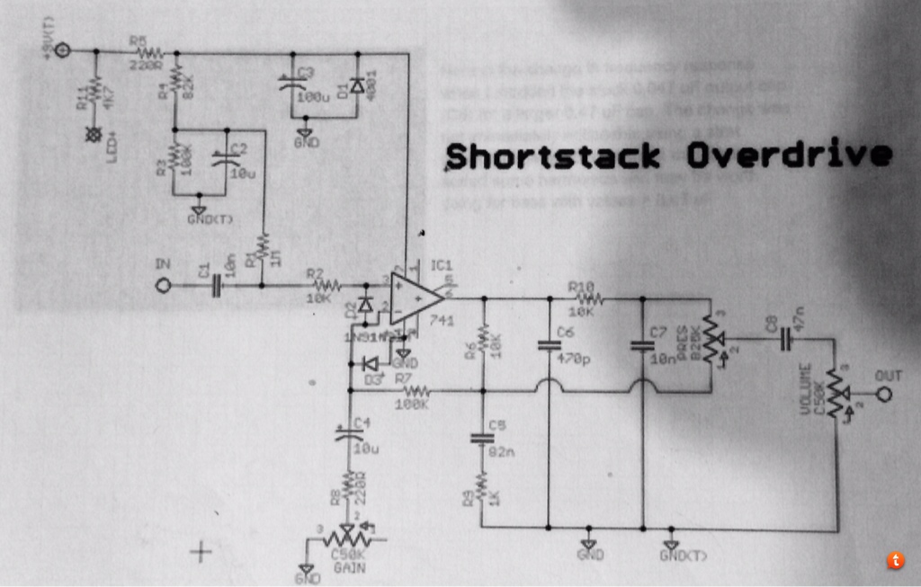
One of the older projects at Madbean pedals is a Hotcake clone (the Shortstack Overdrive), and the project documentation describes the "bluesberry mod":
http://www.madbeanpedals.com/forum/index.php?topic=14265.msg132649#msg132649 The schematic is shown below. For the bluesberry mod, simply insert 1n914 (1n4148) diodes between pins 2 and 3 of the IC and pin 2 and ground, with the orientations shown. It's supposed to smooth out the decay. The documentation also says to try other single op amp ICs (e.g. TL071 or NE5534) to achieve better note decay. I've built the Effdub Flapjack, and it sounds OK to me. I may experiment with that one and try out the bluesberry mod to see if it makes any difference.  |
|
That's an interesting mod... does it work with any op-amp based circuit? Could be a handy design tool.
Through all the worry and pain we move on
|
|
ALERT - the schematic I had before had the diodes in the wrong orientation! I updated the schematic to one I believe to be correct.
Silver Blues - I was thinking about how this mod is supposed to work. An op amp tries to keep the voltage the same at the + and - inputs. It does so by changing the output voltage if there is a feedback connection (which there always is!). The diode from input to ground won't do anything unless a REALLY large voltage spike occurred since it is always reverse biased. The diode across the + and - inputs would potentially limit noise spikes (i.e. a transient voltage difference between the + and - inputs) greater than the forward voltage. It would seem to me that you would want to have a back to back diode pair between pins 2 and 3 to act as a limiter, and possibly with a lower forward voltage. Anyhow, it would be easy to experiment... |
|
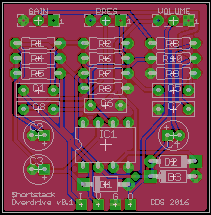
34.9mm x 35.5mm

Yeah, 220, 221. Whatever it takes.
|
|
In reply to this post by Frank_NH
If it works the way you propose, then I should think that a lower Vf diode like a Schottky or germanium would have more of a tone-shaping effect in this position as it would begin to limit transients at a lower threshold. I am however a bit skeptical about that mechanism because if the second diode limits at a lower threshold than the first, then surely the first one serves no purpose?
Presumably this is a similar scenario to the thermal stabilizer diode for germanium transistors, for which I have proposed a mechanism that seems reasonable but fails to explain why this diode has an effect on the tone of the amplifier (based on my theory it should not).
Through all the worry and pain we move on
|
|
In reply to this post by Thorquil
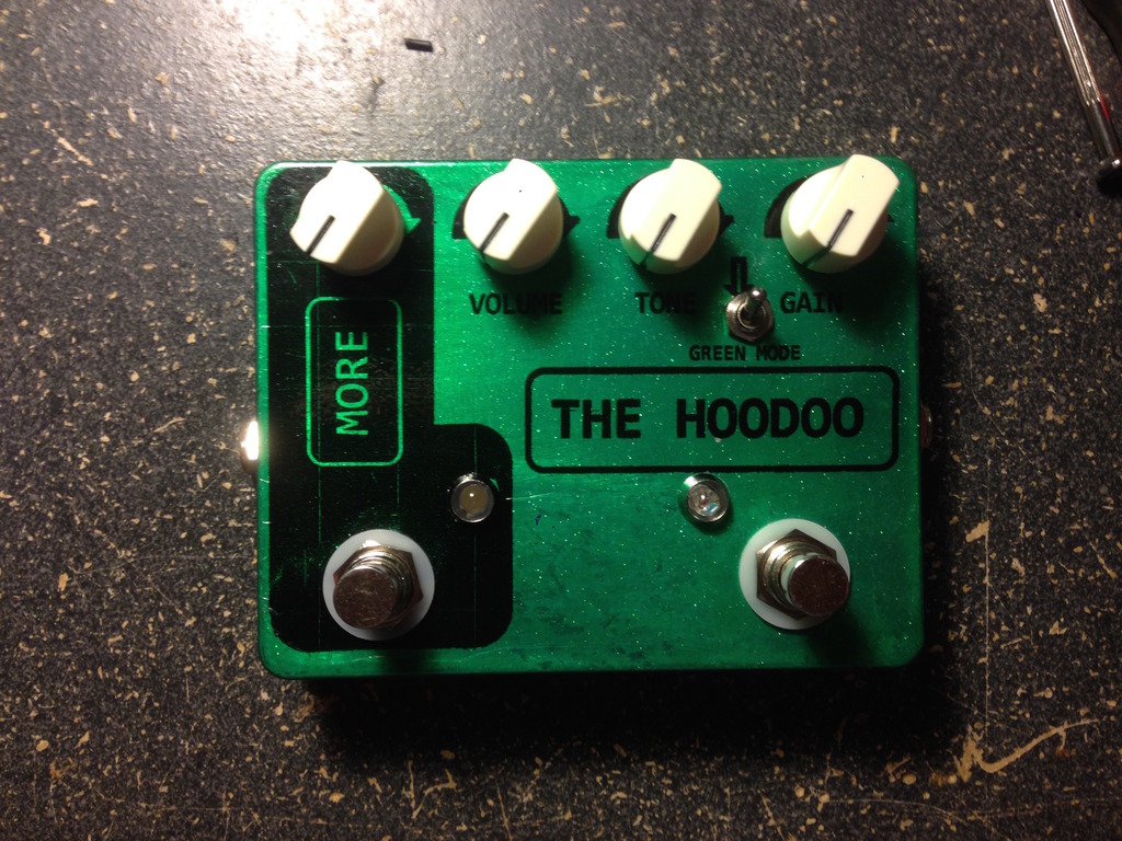
I would like thank you all for your help. This has been an interesting build, and my first and last experiment with waterslide decals (time to learn the toner transfer method). Anyway, thought you might like to see the final product.
 P.S. The more side it an EQD Speaker Cranker, quickly becoming one of my favorites. |
|
Good to hear it's working! Looks great though!
Ca I ask what the problem was with the decal? I used to hate it myself too. Like really, it would wrinkle and tear and was so frustrating. If this was your problem, and you wouldnt mind experimenting another time, you could try this: Mainly because I have an inkjet printer, I have to spray the decal with clearcoat before applying. I figured that was the key to succes.Well, for me. If you spray it just enough, the decal gets a lot stiffer and is a million times easier to apply. You can slide it right off. The seethrough ones though. Th white decals are just horribly fragile things. Ofcourse these could have been nothing of your problem and you can ignore everything I said 
|
|
Administrator
|
Looks great to me man. Like marbles I don't do waterslides, mostly because I've got sausage fingers and end up destroying them when trying to apply them.
Btw, what did you put on the switch? Curious to know if you put different diodes on it, and what you found through your experimenting. Hoping different diodes make a difference in tone or distortion, cause it would be a real nice tweakable effect. |
|
In reply to this post by Marbles
Yes, if you don't spray a couple of thin coats of lacquer on the decal, not only is it very fragile, but the ink just slides right off it too!
|
|
In reply to this post by Thorquil
The switch lifts the diodes, so it is like the regular Hotcake. I did test some different diodes, the difference was minimal, but I ended up going with some 1n34a's.
|
|
Administrator
|
«
Return to Open Chat
|
1 view|%1 views
| Free forum by Nabble | Edit this page |

