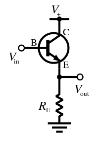
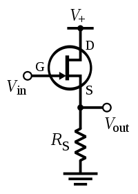
About the buffers, most buffers will be emitter or source follower amplifiers if you're using a BJT or JFET circuit, so they'll look like some variation of this:


and if it's an op-amp, you'll see the inverting input connected directly to the output, with nothing (or maybe just a resistor) between them, like this:

As for the diodes: in a clipping circuit, the voltage drop of the diodes determines at what voltage the input signal waveform will be clipped. So, if you have two diodes in antiparallel with forward voltages of, say 0.7V, then your signal will be clipped at +/-0.7V. If you have mismatched diodes, for example a 4148 and a red LED, you could see clipping at +0.7V and -1.2V. Putting more diodes in series with each other actually sums their forward voltages; if you have four 4148s, you'd expect a clipping threshold of +/-1.4V. This will result in a louder signal, because the input waveform has a larger amplitude prior to being clipped. This is why effects with only germanium diodes in their clipping circuits tend to be quite quiet, because a germanium diode can have a forward voltage as low as 0.2V, which doesn't leave much headroom.
Through all the worry and pain we move on