Hybrid SMD/through-hole vero layouts

classic Classic list List threaded Threaded
22 messages Options
12
Reply | Threaded
Open this post in threaded view
|

Hybrid SMD/through-hole vero layouts

induction
Despite all of the generously provided layouts on this site and others, I generally design my own layout for any pedal I build. (Though I did buy a PCB from Madbean for the Harbinger One, and I'm very happy with it.) Until recently, I have been reluctant to share these layouts, not because I wouldn't be happy and even excited to have others benefit from them, but instead because my veros employ techniques that do not fit the design paradigm of the others posted here, and I got the impression that nobody but me was interested in these techniques.

Several years ago I  bought an SMD cap and resistor selection (similar to 
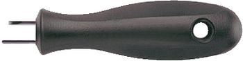
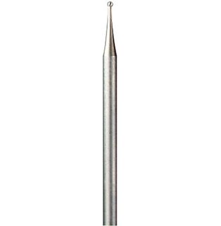
this one), and started designing hybrid veros that include both SMD and through-hole components, with an emphasis on keeping the layouts as small as possible. I design the veros to use as few through-hole caps and resistors as possible, I very often use SMD devices to bridge track cuts, and often employ track cuts between holes (I use a Dremel engraving but to make all of my track cuts these days). When I don't have an SMD component in a value that I need for a given build, I stack components in parallel to construct whatever value is required. (Often, I literally stack them: I solder one right on top of another.)

I assumed that my unorthodox techniques might put others off from using my layouts, especially with the large number of beginners this site attracts to the hobby (which, by the way, I consider to be a great demonstration of the success of the site; good job everybody). But I recently found that Neil's request for a vero of the Valve Wizard U-Boat went unanswered, so I shared my hybrid layout on the off-chance that Neil or someone else might be willing to give it a shot. In that thread, I got a request for more hybrid layouts, so I am now posting a list of all of the hybrid layouts I have designed. Many of them have been built and verified by myself, but many of them haven't. As mentioned above, many of them incorporate mods that I decided on during the breadboard stage. I try to point out those mods in the layout, but sometimes I forget.

Without further ado, here is my list:
- 3-way AMZ jfet splitter
- 4-way op-amp splitter (my own design)
- 6-band graphic EQ (my own design based on MXR 10-band)
- Baja Trembulator
- Bixonic Expandora
- Catalinbread Formula #5
- Daniel Schwartz MultiCab sim
- Diederich Electronics Onyx Wall of Sound Distortion Lo-Fi Fuzz
- Earthquaker Devices Hoof Fuzz
- Harmonic Perk & Jerk (selectable Interfax Harmonic Percolator and Escobedo Harmonic Jerkulator on a single vero, with switchable clipping diodes)
- Klon Centaur
- Lovepedal Purple Plexi 800
- Mad Professor Snow White
- Marshall Speaker Reactance Emulator
- Mictester Secret Sauce Overdrive
- Modular EQ (Design heavily inspired by Phil Abbott's Phabbtone EQ with the option of using an alternate tone stack)
- Multi-PSU power bricks (my own designs)
- Retro Channel The Fuzz
- STM Speaker Saturation Simulator
- Tonepad Neoctavia
- Valve Wizard Engineer's Thumb Compressor
- Valve Wizard Small Time Delay
- Valve Wizard U-Boat
- Vox Repeat Percussion
- Wampler Black '65
- Wampler Ecstasy (aka Euphoria)
- Wampler Paisley Drive
- Wampler Plexi-Drive
- Wampler Tweed '57

If anyone is interested in any of these in particular, let me know and I will post them in Contributions. I would just go ahead and post all of them, but my job keeps me very busy (to say nothing of my 3-year-old son) and I want to do a good job of linking to schematics and other information, and making sure all of the mods are properly documented. Some of these circuits are designed by fellow DIY'ers, and I want to link to their posts in FSB and DIYSB where I found the circuits. Hopefully I will get all of them posted eventually, but at first I will prioritize those that get requests. As much as I'd love to take requests for new veros, chances are slim that I will have time to do them in the near future. (Feel free to post them anyway, but don't get your hopes up.)
Reply | Threaded
Open this post in threaded view
|

Re: Hybrid SMD/through-hole vero layouts

motterpaul
I will read anything you write because you are so knowledgeable.

It looks like you put the SMD parts in the copper side - do you just solder them directly to the copper?

Are they mostly resistors or also other components (like what if so?).

Any tricks to doing that soldering? (I did read about the dremel, but do you need it?)

How much did the resistor/caps assortment cost?

Are you going blind - wearing these yet?

Reply | Threaded
Open this post in threaded view
|

Re: Hybrid SMD/through-hole vero layouts

IvIark
Administrator
In reply to this post by induction
I'd love to see them.  I think the hybrid through-hole SMD is the perfect solution to making the most compact layouts without having to go all SMD, and I personally would much prefer to solder an SMD resistor on the back of the board than to have a standing through-hole resistor.

I've got quite a lot of SMD passives too which I bought in similar packs (0603, 0805 and 1206 sets), and although I haven't used them very much, I would certainly do so if it kept the board size down enough to avoid moving up to a 1590BB for instance.
Reply | Threaded
Open this post in threaded view
|

Re: Hybrid SMD/through-hole vero layouts

rocket88
Administrator
induction i think that's really awesome and inspiring that you've been able to do that. not only do i think it would be a great contribution, but would really love to see them. i think anything that makes building easier, and can help keep board size down is great.
Reply | Threaded
Open this post in threaded view
|

Re: Hybrid SMD/through-hole vero layouts

Frank_NH
I also encourage the SMD layouts.  Generally, I like working with larger components and more spacious layouts, but it would interesting to try out SMD at some point.  And that's a great collection of effects layouts!
Reply | Threaded
Open this post in threaded view
|

Re: Hybrid SMD/through-hole vero layouts

PMowdes

Hell yeah, I'd love to see them.  There's loads of stuff there that I'd  love to build.  Perhaps there can be a new "Hybrid" section in contributions???

Nice work induction
Reply | Threaded
Open this post in threaded view
|

Re: Hybrid SMD/through-hole vero layouts

cylens
same here,

very interested!! i've just started using SMD and it's not that hard... just intimidating at first!
Reply | Threaded
Open this post in threaded view
|

Re: Hybrid SMD/through-hole vero layouts

Alex
In reply to this post by IvIark
That would make larger layouts much smaller!
And now the big question for Mark:
any chance you could design SMD caps and resistors (2 rows span) for V.2 library where you could read values properly?
Is it possible?
I don't have a clue how to do it.
I've tried in the past and...
Otherwise the Panasonic 2.5mm cap may be best for both.
Reply | Threaded
Open this post in threaded view
|

Re: Hybrid SMD/through-hole vero layouts

Hozy31
In reply to this post by induction
Thanks so much induction. I would so love to build all of these. The only one in your list i have built is the klon. Could i request the harmonic perk & jerk.
"Red velvet lines the black box"
Reply | Threaded
Open this post in threaded view
|

Re: Hybrid SMD/through-hole vero layouts

Sergio
Hallo induction, I built some time ago your reverb design and Im very happy with that one. Thank you.
And Id love to see first the saturation and reactance speaker simulation (and to hear your opinion about these ones, or a sample if you have a recording with them)but Id really love to see them all. I used smd in a 9/12/18 volt brick and it worked first time, surprise. So it would be great to see more creative use for smd. Thanks in advance.
Reply | Threaded
Open this post in threaded view
|

Re: Hybrid SMD/through-hole vero layouts

notnews
In reply to this post by induction
wow that's a great library of work you've created here..

I'd love to see all of your layouts posted ASAP haha, but I definitely appreciate your desire to keep things clean and trace-able document- wise. Of all the circuits you posted I think I'd like to see these the most, kept in the order they were listed:

- 3-way AMZ jfet splitter
- 4-way op-amp splitter
- Daniel Schwartz MultiCab sim
- Harmonic Perk & Jerk
- Marshall Speaker Reactance Emulator
- Multi-PSU power bricks
- STM Speaker Saturation Simulator
- Valve Wizard Small Time Delay
- Valve Wizard U-Boat

It was hard to narrow-down that list, man! Every circuit you translated to vero is a gem of a design =)

- thank you for sharing your work. This community is full of people who put considerable time into their work, and absolutely don't have to share.. But people here DO share, and the community grows in population, in information, and in friendliness simultaneously because of it.
Reply | Threaded
Open this post in threaded view
|

Re: Hybrid SMD/through-hole vero layouts

induction
In reply to this post by motterpaul
motterpaul wrote
It looks like you put the SMD parts in the copper side - do you just solder them directly to the copper?
Yes. Look here to see a photo of my U-Boat board.

Are they mostly resistors or also other components (like what if so?).
Resistors and capacitors only. Transistors could probably be made to work, but I haven't tried yet.

Any tricks to doing that soldering? (I did read about the dremel, but do you need it?)
Soldering SMD is really simple. I use a pencil point iron tip, but other tips will work. I also use a helping hands to hold the vero horizontally, copper side up. Here's how I do it:
1. Apply a small amount of solder to one pad
2. Hold the SMD in place with tweezers and re-melt the solder.
3. Push down on the SMD with the tweezer tip and re-melt the solder again so the SMD sits flat against the board.
4. Apply solder to the other pad.

The whole process takes a few seconds per component.

Here are the tweezers I use:


You don't need a dremel, you just need a way to cut the tracks. A drill bit will work for the cuts on the holes, but don't make the cut too large. For the cuts between track you'll need something else: a knife, razor blade, needle file, whatever works for you. I like the dremel engraving bit because I can make very small, precise cuts with it.

How much did the resistor/caps assortment cost?
I spent $10 for something like 1200 components. There's a link in the top post, and another dozen kits from other sellers on ebay.

Are you going blind - wearing these yet?
Since you asked, I'm extremely near-sighted, which means that my far vision is terrible, and my near vision is way better than average. The average person my age has a near point of about 10 inches. Mine is 4 inches. On the other hand, my far point is about 9 inches. I can't make out half inch letters from a foot away without my glasses. I've been like this since I was 10 years old, though. So I can't blame the SMD.

SMD of size 1206, or even 0805, is not super-tiny. At that size, each piece is about the same length and width as the body of a 1N4148. Anyone with decent through-hole soldering skills can probably manage it. Any smaller than that would probably be too small for vero. I can do it easily without optical assistance, in the same posture I use for through-hole. I actually find SMD soldering a little easier than through-hole.
Reply | Threaded
Open this post in threaded view
|

Re: Hybrid SMD/through-hole vero layouts

motterpaul
I am also nearsighted, which means no glasses at the computer, but I do need reading glasses for soldering. I am surprised you use insulated wire for links, though - any reason why?

Yeah - you make it look easy, and the between hole dremel cuts also actually save a lot of board space. I have wondered why no one has found an easier way to make such cuts. I have tried the dremel, but I think you need a really tiny wheel to cut just one strip.

It would be nice if there was another tool to easily make a copper line cut between holes - anyone have any ideas?

Also $10 for a large package of resistors and capacitors is quite a deal -
BTW: I use the same self-holding tweezers for everything, one of the best tools I have found.

I kind of expected to see more components between rows instead of so many row cuts. But if it works for you that's all good.  Why don't you tell us what a good project to get started might be?
Reply | Threaded
Open this post in threaded view
|

Re: Hybrid SMD/through-hole vero layouts

IvIark
Administrator
In reply to this post by Alex
Alex wrote
That would make larger layouts much smaller!
And now the big question for Mark:
any chance you could design SMD caps and resistors (2 rows span) for V.2 library where you could read values properly?
Is it possible?
I don't have a clue how to do it.
I've tried in the past and...
Otherwise the Panasonic 2.5mm cap may be best for both.
I wish it were, but I've tried and it isn't
The resolution just isn't high enough with V2 to allow them to be large enough and still look like realistic representations on the board.

If I were going to do a hybrid layout I'd probably show 3 versions of the board instead of my usual front and bare board only.  In the third I'd use a faded out image of the back of the board so that I could put text next to the passives that is clear enough to read.  Alternatively you could potentially fit a single letter on the passives and then a table somewhere showing each letter and the value next to it.

Of course with a large layout both of these could get untidy very quickly but I haven't thought of a better way of doing it.
Reply | Threaded
Open this post in threaded view
|

Re: Hybrid SMD/through-hole vero layouts

IvIark
Administrator
In reply to this post by induction
induction wrote
Mine is 4 inches.
That's what she said
Reply | Threaded
Open this post in threaded view
|

Re: Hybrid SMD/through-hole vero layouts

induction
In reply to this post by motterpaul
motterpaul wrote
I am surprised you use insulated wire for links, though - any reason why?
Insulated wire isn't required. It's up to the builder. Totally arbitrary.


I have wondered why no one has found an easier way to make such cuts. I have tried the dremel, but I think you need a really tiny wheel to cut just one strip.
Not a wheel, an engraving bit:


Cheap, easy, and effective, lasts forever. I use it for all my cuts now, even when they don't have to be thin.


I kind of expected to see more components between rows instead of so many row cuts. But if it works for you that's all good.  Why don't you tell us what a good project to get started might be?
I have no bias against cuts or links, I have a bias against large boards. I do whatever it takes to make the boards small, which means I'd rather use an SMD component than a through-hole component. This strategy lends itself toward track cuts since SMD can't span more than two rows. My general approach is to condense the circuit around the IC's or transistors and use through-hole components as links between pins that are more than one row apart. It's a different kind of puzzle than a traditional vero.

As for getting started, I'd say choose a circuit you want to build and give it a whirl. I'll keep posting more, as I have time, with preference given to requested circuits. Next up is the Harmonic Perk & Jerk.
Reply | Threaded
Open this post in threaded view
|

Re: Hybrid SMD/through-hole vero layouts

induction
In reply to this post by IvIark
IvIark wrote
induction wrote
Mine is 4 inches.
That's what she said
Ok, maybe 4 and a half.
Reply | Threaded
Open this post in threaded view
|

Re: Hybrid SMD/through-hole vero layouts

Travis
Administrator
Induction - You are my vero hero. Love all your posts dude!
Reply | Threaded
Open this post in threaded view
|

Re: Hybrid SMD/through-hole vero layouts

rocket88
Administrator
induction i'll make a verified section for the hybrid boards. they really look awesome. really great work.
mug
Reply | Threaded
Open this post in threaded view
|

Re: Hybrid SMD/through-hole vero layouts

mug
In reply to this post by motterpaul
Very intersting - although I dont't think my skills are advanced enough yet to take this step...  I'll definetly follow this thread!

motterpaul wrote
It would be nice if there was another tool to easily make a copper line cut between holes - anyone have any ideas?
Somtheing like this? I've seen this tool in a shop here in germany, it's supposed to make a cut in a fixed distance relative to the hole where the longer of the two needles is placed - don't know if this would be between two holes, but it looks like that could be easily adjusted:


Shop is here: Leiterbahnunterbrecher (CONRAD)

However I think 6€ is a bit much for something this simple... should be possible to DIY that as well.
12