I built a thing


|
This post was updated on .
It's the ROG JFET matcher and the germanium transistor tester, all in one self-contained unit.
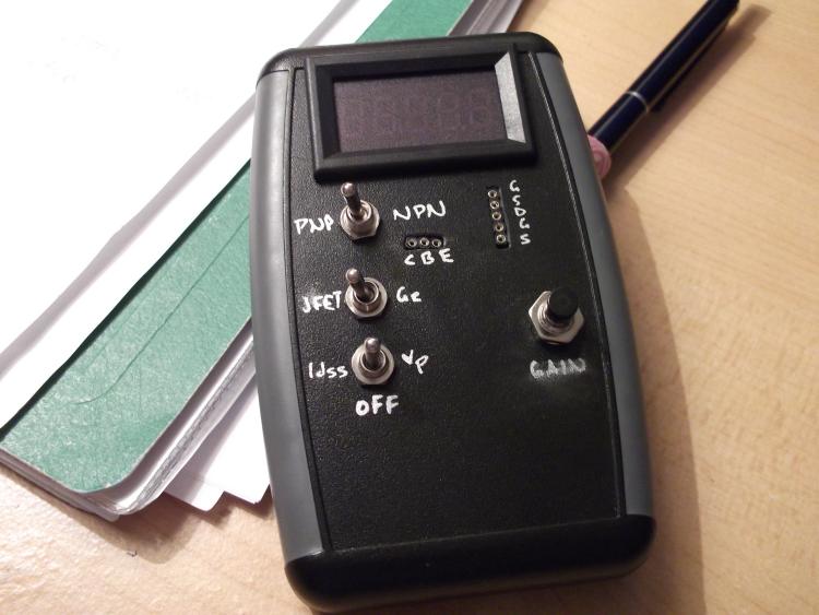   It does both PNP and NPN Ge BJTs and N-channel JFETS. I'm not even going to show you guys the DEFCON-1 level disaster of wires inside  My dad says it isn't that bad but it kind of is. I'm frankly surprised I managed to fit all of that stuff in such a small space. I did the markings in some metallic silver art marker, it looks good but I'm having my doubts about the durability. My dad says it isn't that bad but it kind of is. I'm frankly surprised I managed to fit all of that stuff in such a small space. I did the markings in some metallic silver art marker, it looks good but I'm having my doubts about the durability.
So using this thing, I discovered that the Ges that I got last month have almost zero leakage, and gains from 60-110. I was super happy about that  Total cost was ~$20 I'd estimate, plus a healthy coating of plastic dust all over everything.
Through all the worry and pain we move on
|
|
Administrator
|
I got to say, that looks awesome. My only question is when can I get one.
|
|
|
Excellent!
 I need to put my JFET tester into a more permanent housing to make it a little more user friendly. The main thing I want to add is a 9V jack so i can get a uniform supply voltage. Right now I use a battery, which often is not exactly 9V! Remember though that even ballpark numbers for Vp and Idss are good enough for application purposes. BTW - I have an updated version of my JFET spreadsheet. I added gain calculations which assume the source resistor is either: (a) fully bypassed by a large capacitor or (2) unbypassed. The gain increase that the capacitor provides is significant (at least 2X). I'll plan to post it soon for download. |
|
|
In reply to this post by rocket88
Thanks lol. It's really handy and adds some portability. I could tell you how to build it if you like
The switch wiring is a bit confusing though. I also left the schematic... somewhere...
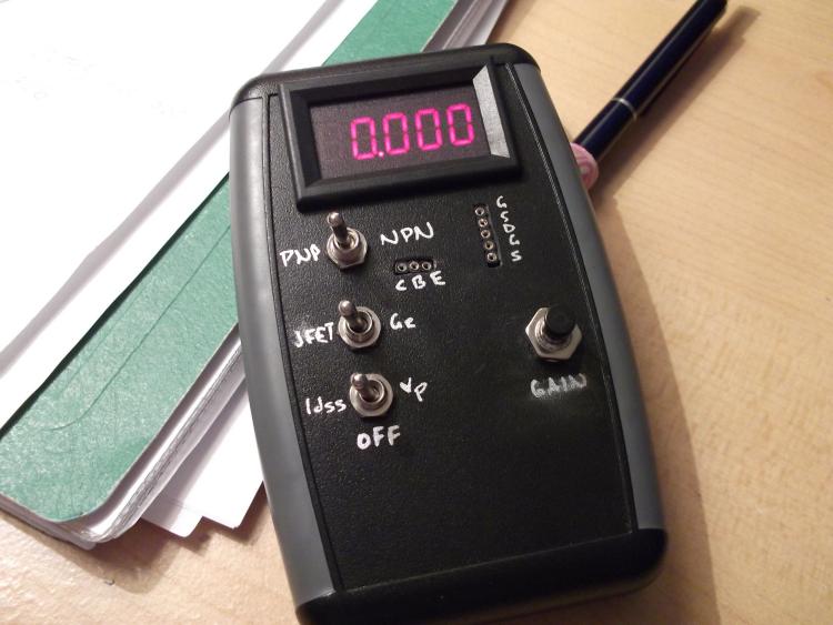
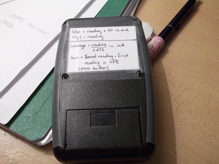
The centerpiece of this project though is the DVM module that makes it possible in the first place. I used one of these, which is a little different (and better) in real life than the picture they use. The one I received was 0-33V with a floating-decimal five-digit display, which is more than perfect for this application. Idle it sits at 0.000v as you'll notice so you get a resolution of 0.001V below 10V. It also comes with a nifty frame. The page lists the input impedance as "over 100KΩ" which is extremely vague, but I compared its reading to that of my full-sized multimeter and the readings were within 0.002V of each other so I'm calling it good. It doesn't look like it has any issues with ROG's circuit (they call for >1M input impedance). I'm going to try and describe it without looking at my schematic... Firstly, the bottom switch is both the global power and the mode switch for the JFET tester. It is a DPDT center off, where obviously the center is off. One pole has +9v on lugs 1 and 3 and the whole tester essentially takes power from lug 2. Left position on mine is Idss and right is Vp, using the other pole on the switch. This way, there is no power applied to the tester in the off position and I don't need a separate switch for the power. The middle switch switches testers. The DVM module has a separate positive test lead and a ground lead that is also the negative test lead. So the switch essentially swaps the test leads from the JFET tester to the Ge tester. It is a DPDT on/on. This is where it gets confusing. The default setup for the Ge tester only tests PNPs. While this is all well and good, I wanted a comprehensive solution for tricky transistor testing (ha). So what I did was that I connected a third (the top) 3PDT on/on switch following the second switch to switch between NPN and PNP. First pole of this switch swaps the polarity of the positive test lead. Second pole swaps the polarity of the negative test lead. Third pole switches the input voltage of the tester from positive to negative. I have an ICL7660S voltage inverter in there to provide the -9v power for the NPN mode while keeping the rest of the tester active and unchanged. The momentary switch is obviously just the mode switch for the Ge tester. You hold it down and read the meter then apply the calculation I have so professionally taped to the back of my build  . .
So yeah the whole unit is self-contained and powered off a 9v battery in a fancy case, haha. I had to manually cut the square ("square") holes for the sockets and meter - the meter frame has integral clips that just snap in and I hot-glued the circuits themselves to the inside of the front panel to keep them in place. Finagling the trimpot for the Ge tester was a bit of a hassle (kinda didn't think the placement through 100% then bent the leads wrong) but it ended up alright. I'm happy with it anyway  I'll post the schematic if and when I find it, and provided you can decipher it. I'll post the schematic if and when I find it, and provided you can decipher it.
Through all the worry and pain we move on
|
|
Administrator
|
If you have a schematic or layout I'll build one or........
 Also, thanks for the first spreadsheet and the new one. I'll have to get it.
|
|
|
Bahaha yeah I'll see if I can find that blasted schematic. I just built the two tester layouts separately but I'm sure you could integrate them into one board without much issue.
Through all the worry and pain we move on
|
|
|
In reply to this post by Silver Blues
That is great.!
I thought this would be a great place to ask if someone could point me in the direction of the formulas needed to measure these values. I have a meter that reads hfe. I have also built the "greatly improved jfet marcher" I just don't know the formulas to match them.
Give a man a match and he'll be warm for a day.
Set a man on fire and he'll be warm for the rest of his life. |
|
|
An hFE meter won't tell you anything about JFETs, it's designed specifically for BJTs, and silicon ones at that. It will measure germaniums but the reading will be way off because it doesn't compensate for the leakage (or provide any way to read it).
As far as matching FETs, in the case where you need them matched, you just need to make sure the Vp and Idss are the same. What you're really doing with this thing is making sure you use the right resistances to bias each FET correctly. Frank can tell you a little more about that I guess, he's been the one running numbers for us these days
Through all the worry and pain we move on
|
|
|
Aha I found the schematic!
I'll see if I can scan it or digitize it for you tomorrow Rocket. Scan will give a bigger picture (this forum is weird when it comes to attaching pics) but I don't know whether you'll be able to read it XD IDK we'll see.
Through all the worry and pain we move on
|
|
|
This post was updated on .
"I have also built the "greatly improved jfet marcher" I just don't know the formulas to match them."
You don't need any formulas to use the JFET information. I'll try to condense my thoughts into a short essay. First, for the JFETs, you just need to measure the drain saturation current, Idss, and the pinch-off voltage, Vp. How to do that is described in the post here on the improved JFET matcher. You can compare your numbers with the typical ranges from the data sheets. What you'll find is that these parameters can vary quite a bit, but always within the ranges specified on the datasheets (if they are out of range, the JFET may be bad and should be set aside). Now, why do you want to do this? Can't I use any old J201 or 2N5957 in my favorite circuit? Well, the answer is - that depends.  Some circuits applications aren't too fussy about the JFET parameters. One such circuit is the JFET buffer (or source follower), seen in many effects to buffer the input or output. (You also see similar configurations with BJTs - the so-called emitter followers). The buffers have near unity gain, and so as long as the JFET's parameters are in the ballpark, you're probably good to go. Amplifier applications of JFETs are different. Many overdrives, distortions, and amp sims need Idss and Vp to be in a narrow range to bias properly and provide the needed signal gain. A good example is the original Wampler Plexidrive. If you built the original Plexidrive vero layout and your JFETs were not in the right range it didn't work well. To help bias this kind of circuit and enable it to work properly, trimmers can be substituted for the drain resistors, which then allows the use of JFETs with a wider range of Idss and Vp. This was done to the Plexidrive, as you can see if you look up the second version of the Plexidrive here. Even though specific values of Idss and Vp aren't as important when trimmers are used for the drain resistors, I feel you should try to at least have a set of JFETs with similar Idss and Vp. This is what JFET matching is all about - we don't necessarily care about the specific values of Idss and Vp and long as all the JFETs have similar values. The JFET tester allows you to go through a bucket of (now more expensive!) JFETs and match them according to their parameters. Now, can you actually predict what Idss and Vp you need to bias a given JFET amplifier circuit? The answer is YES! That's what my JFET spreadsheet is all about. The math isn't hard, but it's complicated enough and a spreadsheet is a great way to organize the calculations. So, given the source and drain resistors (and/or the desired drain bias and supply voltages), you can calculate if a JFET with a given Idss and Vp will work. I did this for the original Plexidrive (without trimmers) and had no trouble getting the circuit to work. That's because I had tested my available J201s beforehand and knew which ones to use. By the way. Brian Wampler used this very same approach when manufacturing the original Plexidrives (i.e. choosing JFETs to match the circuit). So the bottom line? Test all you JFETs, label them and record their Idss and Vp in a log. When it comes time to use them (either matched sets or specific values of Idss and Vp), you'll know what you have and can apply them with confidence. And I've only just scratched the surface. There a many other JFET applications in effects pedals, and it would probably require a book to list them all (e.g. mu amps, SRRP, ...). But in all cases, knowing your JFET data is essential if you don't want to have to go through a bucket of transistors hoping you can find one that works. OK, so this wasn't a short essay...
|
|
|
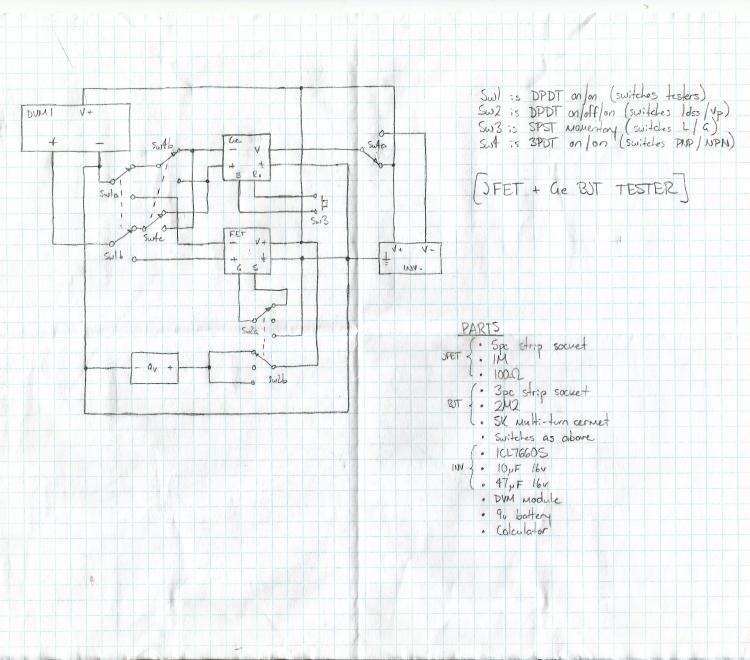
Alright, here's the schematic for my tester. Sorry about the kind of poor quality
I did it in drafting pencil on a whim and then lost it then found it then folded it and it got crinkled in my pocket floating around with some dice. LOL
Through all the worry and pain we move on
|
«
Return to Open Chat
|
1 view|%1 views
| Free forum by Nabble | Edit this page |