It's taken a lot...but getting frustrated...a simple request...

classic Classic list List threaded Threaded
22 messages Options
12
Reply | Threaded
Open this post in threaded view
|

It's taken a lot...but getting frustrated...a simple request...

rtman26
Ok, so I have a question:

I've assembled a few veros (don't exactly remember which ones...all BC108/9 fuzz-es because thats the  type of Qs I have) and NOT A SINGLE ONE works.  When "off" they all bypass the clean signal to my amp, but when I click them on (the led's come on) but NOTHING comes out of my amp.  I have double and triple checked for orientation and bridging...it's all fine.  

Here's my main request....can someone please attempt to build this fuzz so I know the layout is right..?
It should only cost a few dollars.  Hell, I would mail you the parts if the shipping wouldn't cost more than the parts themselves....

Silicon Fuzz Face

It's very simple and all I did was change to a 3pdt and wire an LED to the center poles.  

Taking a look at the layout, I'm finding it odd that the E of Q1 is wired to the sleeve(which is fine), but then jumped back to the - of c3.  That whole ground-c3-fuzz pot layout seems logically wrong but I really am new to this so I could just be looking at it all wrong.  

Advice would be appreciated....thanks!
Reply | Threaded
Open this post in threaded view
|

Re: It's taken a lot...but getting frustrated...a simple request...

Vince
This one definitely works if you're looking for a small one and all Marks work on this blog.

Reply | Threaded
Open this post in threaded view
|

Re: It's taken a lot...but getting frustrated...a simple request...

GoranP
In reply to this post by rtman26

If not a single one works and you've used layouts from this or Harald's site, I'd say its quite likely that your wiring is somehow wrong.

If you don't mind posting pictures of your wiring/boards, it's also quite likely we'll be able to sort it out.
Reply | Threaded
Open this post in threaded view
|

Re: It's taken a lot...but getting frustrated...a simple request...

rtman26
I just realized my link takes you to the wrong picture.  

Correct fuzz layout

this is the one I was talking about with the odd Q1/C3 loop.  I've tried taking pictures of the solder joints on the backs of my boards but none of the cameras I have take good enough pictures.  At this point I've switched things around so much, trying different things, that I've gotten myself confused as to what's what.

 I'll just order some diodes (because my local radio shack closed ) and try the one above and let you know.  Thanks
Reply | Threaded
Open this post in threaded view
|

Re: It's taken a lot...but getting frustrated...a simple request...

GoranP
You're probably trying to get in closer than your lens' minimum focal distance. Try "macro" setting or just move your camera further out. Even blurry pics might do to check if at least your wiring is ok.

Eventhough I really don't need another fuzz (am I allowed to say that around here? ), I'll build this tonight just for laughs and let you know tomorrow.

Also, diodes? I know you can use bjt as diodes, but diodes as transistors?
Reply | Threaded
Open this post in threaded view
|

Re: It's taken a lot...but getting frustrated...a simple request...

rtman26
This post was updated on .
I have since completely disassembled the board to try again...so I can't give you pics of the board.  

I was referring to the layout Vince posted....it has a diode (D3) towards the top of the board.  But if you would build the one I posted...that would be awesome.  I haven't been able to get anyone to verify it.

Here's my box wiring.  

off board

Ignore the wire from v3, it was for a different board I tried.  I have also removed led resistor just to get unimportant junk out of the way.  

I'm using the stereo 1/4 as in and the mono as out, and the bottom right lug on the switch(sorry the pic is sideways)....the white wire....would go to the board input (at least in my brain).  Also, it looks kind of like F3 and V1 are connected by the same wire...but neither of them is connected to anything....neither is 9+.  

You see anything screwy with this?  
Reply | Threaded
Open this post in threaded view
|

Re: It's taken a lot...but getting frustrated...a simple request...

GoranP
This post was updated on .
rtman26 wrote
Ignore the wire from v3, it was for a different board I tried.  I have also removed led resistor just to get unimportant junk out of the way.  
OK, just to be on the same page... I number my pots like so


When you say V3, do you mean that white wire going off the picture to the right? Just so I know, I'd call that V1.

The actual footswitch wiring seems ok even though you apparently don't ground the circuit input while in bypass. Other than that, your signal wiring seems to be fine (as long as the circuit's output is indeed volume pot middle lug, which is not always the case).

EDIT: just noticed this, as I don't put battery jacks in any of my pedals but then again you don't have a dc jack :)... why are your battery negative and f5 wired to a different input lug than your jacks' grounds? Grounds should all go to the ring of the input jack, whichever tab that is, if you need to do power switching (dc/battery). If you don't, just use the sleeve and connect all grounds to that (like the output jack).
Reply | Threaded
Open this post in threaded view
|

Re: It's taken a lot...but getting frustrated...a simple request...

black_out
In reply to this post by rtman26
First off, a lot of people will recommend that you test your build without the switch before you box it up, that way if you're having problems, you know it's not your switch wiring. I definitely recommend this in the future. It'll also allow you to build up a circuit and decide whether you like it or not before you go to the trouble and expense of boxing it up.

Looking at your offboard wiring.  The black wire from the battery clip should be going to the center lug on the input jack. You have it wired to the tip. I'm not sure exactly what's going on with the rest of your wiring without seeing the board but I recommend desoldering everything you have going on there and starting from scratch using lvlark's offboard wiring guide on this page. It's also worth noting that you have something wired to the ring on the input jack, which is also part of your problem. If you're only going to be using a 9v battery clip you don't really need a stereo jack for the input. that's not to say you can't use one, you just don't need the ring.  So in this situation the 9v+ from the board should go to the +(red) lead on your battery clip, and the negative lead on the clip should go to ground, which will be the center lug on your stereo jack. Like I said, try rewiring everything using lvlark's guide and let us know how you make out. If you're still having problems, post some pictures and we'll see if we can help you sort it out.
Reply | Threaded
Open this post in threaded view
|

Re: It's taken a lot...but getting frustrated...a simple request...

GoranP
black_out wrote
Looking at your offboard wiring.  The black wire from the battery clip should be going to the center lug on the input jack. You have it wired to the tip. I'm not sure exactly what's going on with the rest of your wiring without seeing the board but I recommend desoldering everything you have going on there and starting from scratch using lvlark's offboard wiring guide on this page. It's also worth noting that you have something wired to the ring on the input jack, which is also part of your problem. If you're only going to be using a 9v battery clip you don't really need a stereo jack for the input. that's not to say you can't use one, you just don't need the ring.  So in this situation the 9v+ from the board should go to the +(red) lead on your battery clip, and the negative lead on the clip should go to ground, which will be the center lug on your stereo jack. Like I said, try rewiring everything using lvlark's guide and let us know how you make out. If you're still having problems, post some pictures and we'll see if we can help you sort it out.
His battery black wire does go to the middle lug because it's also connected to the input ring. That in itself is a mistake and the entire ring should be taken out of the picture (unless he's using both dc and battery) and that ring "ground" needs to be connected to the sleeve.
His input tip is correctly wired to the footswitch which then takes it to board input (white wire going nowhere).

I agree on not needing stereo input jack in this situation and also agree on just testing the barebones circuit before boxing it. Perhaps building a test enclosure might help...

And also, I second the idea that he should switch to Mark's offboard wiring. It's bulletproof and the extra grounding is a great feature.

Reply | Threaded
Open this post in threaded view
|

Re: It's taken a lot...but getting frustrated...a simple request...

rtman26
In reply to this post by black_out
Goran- I number pots the same way you do, and I'm referring to the white wire going to the output ground.  Basically disregard wires coming off of pots, because the signal flow is kind of useless without the board.  I originally had the input grounded in bypass, but I took out everything that was unnecessary in order to help isolate the problem.  

Black_out-  Just to make sure I'm not over-simplifying...testing without the switch would just mean I wire the input tip to the input of the board...correct?  

The picture is a little confusing because of the low quality, but the 9- is wired to the ring, not the tip.  Which like you said, I don't need...but it keeps me from having a lot of wires globbed onto the same lug.  I didn't think it would cause a problem and I only used it because the original layout called for one (even though they had the input/output on the wrong sides).  If you think changing to a mono will help me, I'll gladly do it.

Thanks for the replies!

Reply | Threaded
Open this post in threaded view
|

Re: It's taken a lot...but getting frustrated...a simple request...

GoranP
rtman26 wrote
The picture is a little confusing because of the low quality, but the 9- is wired to the ring, not the tip.  Which like you said, I don't need...but it keeps me from having a lot of wires globbed onto the same lug.  I didn't think it would cause a problem and I only used it because the original layout called for one (even though they had the input/output on the wrong sides).  If you think changing to a mono will help me, I'll gladly do it.

Thanks for the replies!
I can see that 9 is going nowhere (board input) and that's ok. What I'm proposing is to have all the grounds connected together, somehow. In your case it means moving all the black wires to input sleeve. You can avoid the "globbing" by daisychaining like in Marks layout.
Mono jack is all you need unless you need dual power source.

In a nutshell, all grounds should be connected and on your picture that's not the case.
Reply | Threaded
Open this post in threaded view
|

Re: It's taken a lot...but getting frustrated...a simple request...

rtman26
I don't know how I didn't see that offboard wiring diagram before....but I'll give it a try in the next few days.  Thanks again.  
Reply | Threaded
Open this post in threaded view
|

Re: It's taken a lot...but getting frustrated...a simple request...

black_out
In reply to this post by rtman26
yeah, just omit the switch altogether. So the output from the board goes straight to the output jack and the input on the board comes straight from the input jack. Otherwise you just wire everything else as normal. Some people use a test box to do this, but honestly I just wire it all together loose. It looks like a giant rats nest, and it does create a little more work in the long run, because you're going to want to go back and trim the leads based on the correct spacing  and  resolder them once it's in the enclosure, but it does allow you to eliminate a variable if you need to trouble shoot, and it saves you of the headache of buying/drilling/painting/etc an enclosure for a circuit that you may very well find you don't like. I find it's also easier to experiment with whatever components you might have socketed with the board lying out in the open in front of you.
Reply | Threaded
Open this post in threaded view
|

Re: It's taken a lot...but getting frustrated...a simple request...

GoranP
In reply to this post by rtman26

@rtman: here you go, as promised. I just finished building this and it works fine (whatever that may sound like :) ). I used 2n3904 and B1k for fuzz pot 'cause that's all I had but the circuit is verified.


I even wired it exactly as your schematic so there's no funny business 
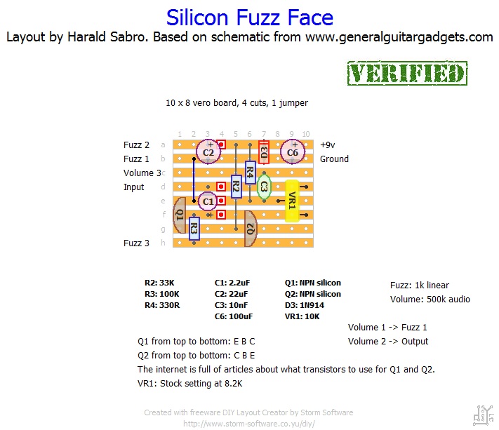
. Normally I'd use Mark's offboard wiring.


There's nothing stopping you from having a fully functioning fuzz now...
Reply | Threaded
Open this post in threaded view
|

Re: It's taken a lot...but getting frustrated...a simple request...

induction
In reply to this post by black_out
black_out wrote
It's also worth noting that you have something wired to the ring on the input jack, which is also part of your problem. If you're only going to be using a 9v battery clip you don't really need a stereo jack for the input. that's not to say you can't use one, you just don't need the ring.  So in this situation the 9v+ from the board should go to the +(red) lead on your battery clip, and the negative lead on the clip should go to ground, which will be the center lug on your stereo jack.
I have to disagree with this.  The purpose of the stereo input jack is to disconnect the battery when you unplug the input by connecting the battery negative lead to the ring.  When you put a mono plug into a stereo jack the ring is grounded and current flows.  When you unplug, the ring is no longer grounded and the battery is disconnected.  If you use a mono jack, the pedal will be powered even when you aren't using it, and you will have to remove the battery to avoid draining it.

I believe you may be confusing input jack switching with DC jack switching, which is designed to disconnect the battery when an adapter is plugged in.
Reply | Threaded
Open this post in threaded view
|

Re: It's taken a lot...but getting frustrated...a simple request...

induction
Regarding my last paragraph: more likely you are thinking of the fact that a stereo input jack is not necessary for adapter-only wiring (no battery).  This is correct.  

If this is getting too confusing, maybe this will help:
adapter only: mono (but stereo doesn't hurt anything)
adapter and battery: stereo
battery only: stereo
Reply | Threaded
Open this post in threaded view
|

Re: It's taken a lot...but getting frustrated...a simple request...

black_out
You're absolutely right. I thought it about later in the day and realized my mistake. It's been a while since I wired anything with a battery clip. I guess I shouldn't reply to messages before my second cup of coffee!
Reply | Threaded
Open this post in threaded view
|

Re: It's taken a lot...but getting frustrated...a simple request...

GoranP
In reply to this post by induction

@Induction: excellent points all around.

I keep forgetting to mention such things on account of

- I only ever use dc power and more importantly
- I always unplug power when I'm done playing.
Reply | Threaded
Open this post in threaded view
|

Re: It's taken a lot...but getting frustrated...a simple request...

rtman26
Thanks for all of your help guys.  I switched to Mark's offboard, put in a mono jack and  got it working today(but I plan on putting the stereo jack back in to save the battery).  When I looked over everything I noticed I'm a dumbass and completely neglected a wire off of the baord....

But that brings me to a couple more questions:

The output seems very low and the signal kind of ......warbles......If that makes any sense.  I've heard these things can oscillate, I'm just curious as to what's causing it.  

I'm also using bc108 transistors but I have 2n7000s....any improvement there?

Lastly, when I only have disc caps in .01u....should I replace with film?

Again guys...thanks for helping me trudge through my first build.  
Reply | Threaded
Open this post in threaded view
|

Re: It's taken a lot...but getting frustrated...a simple request...

Vince
The fuzz face doesn't have much output and the fuzz doesn't really sound decent unless cranked so it sounds like it's doing what it should. Boxing it can sometimes cure noise etc as the enclosure will act as a shield of sorts.
12