JHS Little Black Buffer

classic Classic list List threaded Threaded
19 messages Options
Reply | Threaded
Open this post in threaded view
|

JHS Little Black Buffer

hahafender
I have pics here of the front and back of the JHS Little black buffer. I was wondering if anyone can trace it and make a vero layout. the electrolytic is 10uf. and the caps say 'u1k100' on them. im assuming that means 100nf. the IC is a TL072.

Thanks!!


Reply | Threaded
Open this post in threaded view
|

Re: JHS Little Black Buffer

IvIark
Administrator
Can you try to take a sharp close up of the board, preferably higher resolution, and will you pull those bits of hot glue or whatever off the back.  I've got the values but can't see the connections on the back of the board clearly.  Also what opamp is it?
Reply | Threaded
Open this post in threaded view
|

Re: JHS Little Black Buffer

hahafender
It's a TL072.
Ill try to take that glue off late tonight and take a better pic. sorry about that
thanks for the response!
Reply | Threaded
Open this post in threaded view
|

Re: JHS Little Black Buffer

hahafender
In reply to this post by IvIark
here's the best i could do with my lil iphone. hope it's good enoguh


Reply | Threaded
Open this post in threaded view
|

Re: JHS Little Black Buffer

IvIark
Administrator
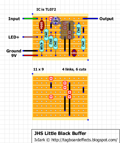
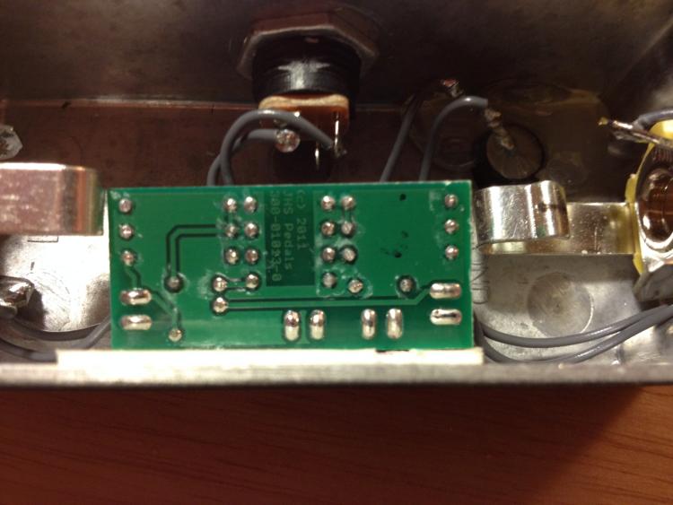
Well this is a bit of a guess because some of the tracks aren't visible and so I've assumed some things.

100n input cap, 10u output cap, 2M2 pulldown resistor and 2 x 2M2 voltage divider at pin 3 I am confident are correct.  

So on to my guesswork:

The buffer has an LED and the 470R is the only value suitable for a current limiting resistor (unless there is another resistor offboard inline with the wire going to the LED?)

The 2 x 2M2's at pin 5 I think is simple a voltage divider for the non inverting input of an unused channel with the inverting input and output then linked, and so that channel performs no function but by using this method on an unused channel it means no noise will be introduced by it.  I have no idea why he would do this.  It may just be a case of using a TL072 because he has them in stock for some of his other pedals and so he buys in bulk and gets better prices.  But if he used a TL071 instead of the TL072 then he wouldn't need those two extra 2M2 resistors.

That leaves the 100n which I can't see much use for on that side of the board other than a power supply filter cap.

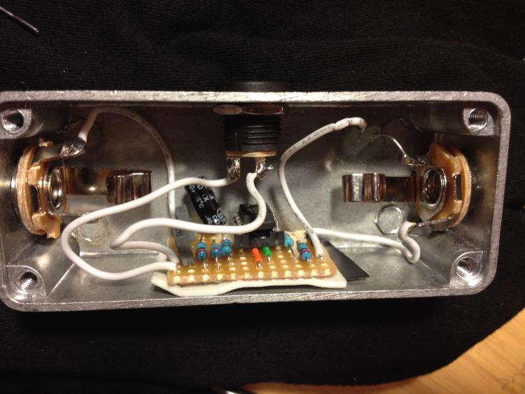
This will definitely work as a buffer and so it's my best guess based on what I can see.  If someone builds it and confirms it as working I'll post it on the blog.

Reply | Threaded
Open this post in threaded view
|

Re: JHS Little Black Buffer

hahafender
yeah, theres no other LED resistor anywhere. ill try this one out as soon as i can and let ya know. thanks for this!!!
Reply | Threaded
Open this post in threaded view
|

Re: JHS Little Black Buffer

IvIark
Administrator
I didn't like the layout so have jigged it around a bit.  It is definitely going to work as a buffer and I think it's accurate so I'll just post the new layout on the blog.
Reply | Threaded
Open this post in threaded view
|

Re: JHS Little Black Buffer

hahafender
you changed the layout?

im not sure i fully understand what you mean/said lol sorry
Reply | Threaded
Open this post in threaded view
|

Re: JHS Little Black Buffer

IvIark
Administrator
Yes I moved things about a bit, now posted on the blog.
Reply | Threaded
Open this post in threaded view
|

Re: JHS Little Black Buffer

hahafender
sweet. just saw it. i already ordered everything to build it, so hopefully everything ships fast and i can verify it for you soon

thanks so much!
Reply | Threaded
Open this post in threaded view
|

Re: JHS Little Black Buffer

IvIark
Administrator
Thanks for the pics
Reply | Threaded
Open this post in threaded view
|

Re: JHS Little Black Buffer

AndyF
hi, built the second version does not work, is dead! something is not right.
Reply | Threaded
Open this post in threaded view
|

Re: JHS Little Black Buffer

IvIark
Administrator
This post was updated on .
Post your voltages.  The left hand side is a generic buffer and it's definitely correct, it's virtually impossible to do wrong.  Exactly like this one from Dano but using a dual channel opamp with the voltage divider buffered by the second channel:


But is uses 2M2 instead of 1M resistors for the voltage divider, which is done on the right hand channel.  Voltage divider at the non-inverting input, inverting input and output linked, and that connected to the non inverting input of the left hand channel by the omitted cut in between 3 and 6.

Your voltages should help us see what's going on
Reply | Threaded
Open this post in threaded view
|

Re: JHS Little Black Buffer

IvIark
Administrator
The only thing I have included in the second layout which isn't in the original is the filter cap at the voltage divider, and although I'm not sure why that might be an issue, maybe it is.  So you could try de-soldering one leg of the bottom right 47u cap and see if that makes a difference
Reply | Threaded
Open this post in threaded view
|

Re: JHS Little Black Buffer

hahafender
something's wrong here with my build. LED doesnt light up... and loud noise when plugged in. is there something wrong with the way i wired it?
Reply | Threaded
Open this post in threaded view
|

Re: JHS Little Black Buffer

IvIark
Administrator
You haven't connected at least one of the jack socket sleeves to ground by the looks of it, which means the sockets, box and LED aren't being grounded.
Reply | Threaded
Open this post in threaded view
|

Re: JHS Little Black Buffer

hahafender
yup. i just figured that out haha. it works buddy. thank you!
Reply | Threaded
Open this post in threaded view
|

Re: JHS Little Black Buffer

IvIark
Administrator
Cool, and another verification
I think I'll build the modded layout tomorrow if I can get a bit of a break from work so I can see what's going on with the problems with that version.
Reply | Threaded
Open this post in threaded view
|

Re: JHS Little Black Buffer

hahafender
cool man!