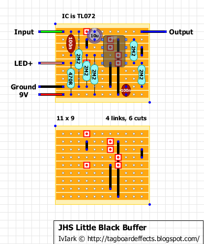
Well this is a bit of a guess because some of the tracks aren't visible and so I've assumed some things.
100n input cap, 10u output cap, 2M2 pulldown resistor and 2 x 2M2 voltage divider at pin 3 I am confident are correct.
So on to my guesswork:
The buffer has an LED and the 470R is the only value suitable for a current limiting resistor (unless there is another resistor offboard inline with the wire going to the LED?)
The 2 x 2M2's at pin 5 I think is simple a voltage divider for the non inverting input of an unused channel with the inverting input and output then linked, and so that channel performs no function but by using this method on an unused channel it means no noise will be introduced by it. I have no idea why he would do this. It may just be a case of using a TL072 because he has them in stock for some of his other pedals and so he buys in bulk and gets better prices. But if he used a TL071 instead of the TL072 then he wouldn't need those two extra 2M2 resistors.
That leaves the 100n which I can't see much use for on that side of the board other than a power supply filter cap.
This will definitely work as a buffer and so it's my best guess based on what I can see. If someone builds it and confirms it as working I'll post it on the blog.
