Jan Ray Schematic Changes vs Bitbox

classic Classic list List threaded Threaded
11 messages Options
Cam
Reply | Threaded
Open this post in threaded view
|

Jan Ray Schematic Changes vs Bitbox

Cam
Hi All,

First try at a DIY pedal like this so likely have a bunch of questions.

Initially I thought I had missing parts (which technically I am missing the 100n) but after contacting bitsbox they confirmed their kit was for the previous version and as such doesnt have the 100n and also has a 1N5817 diode in place of a 5th 1N4148 at D5?

Will these changes make a big difference?

Cheers,
Cameron
Reply | Threaded
Open this post in threaded view
|

Re: Jan Ray Schematic Changes vs Bitbox

induction
No. Neither of these components are in the signal path.

The 100n is a power filter cap. It reduces ripple in the V+ rail. It parallels a higher value (47u) electro, which means that it's not even the main filter cap. It's there to add a little extra filtering at high frequencies where electros sometimes underperform. Without this cap, you will notice little or no difference in performance, except maybe for a very slight increase in background noise. You can easily add this cap to any existing layout that lacks it, if you want to.

D5 is a polarity protection diode. It stops your pedal from dying if you plug in an adapter with the wrong polarity. The layout calls for a 1N4148, which provides protection at the cost of reducing the V+ rail by 0.7V.  The 1N5817 is actually a better choice for this purpose than the 1N4148, as it does the same job while only dropping 0.3V from the rail. The only sonic impact from this diode swap is a slight (probably unnoticeable) increase in headroom. I replace any 1N400x or 1N4148/1N914 polarity protection diodes with 1N5817 as SOP.
Cam
Reply | Threaded
Open this post in threaded view
|

Re: Jan Ray Schematic Changes vs Bitbox

Cam
Thank you for such a detailed reply. Being a complete noob it was very helpful and interesting. Im slowly learning things. I'll report back with any other problems or successes haha. Cheers.
Cam
Reply | Threaded
Open this post in threaded view
|

Re: Jan Ray Schematic Changes vs Bitbox

Cam
This post was updated on .
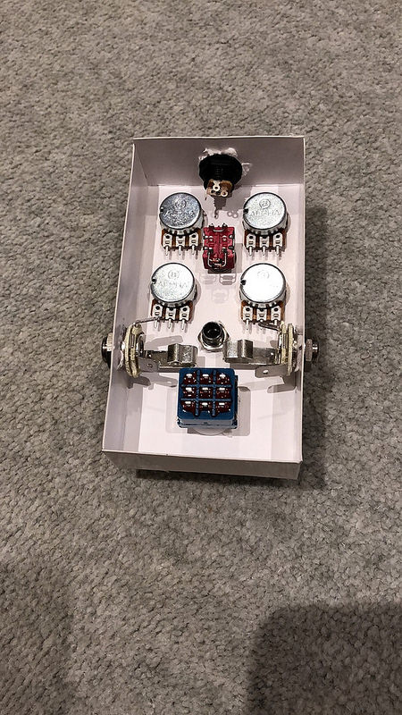
Well just a little update and wondering if this looks ok so far (apart from the below)

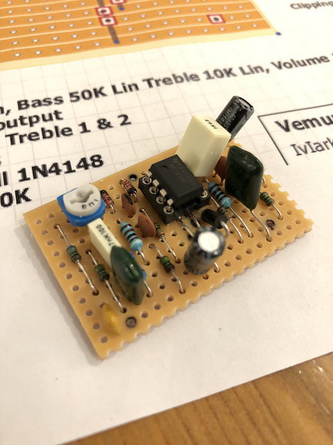
Last night I managed to populate the board, but I woke up this morning in a panic knowing I forgot to check the polarity of the 2 Electrolytic Capacitors. I'll have to revisit and correct their orientation if wrong. I presume the lighter colour on the Electrolytic Capacitor in the schematic indicates the negative stripe on the actual component? If so I can already see from this photo the top one is wrong and knowing my luck they both will be. Hopefully I don't mess things up too bad.

Also I was wondering how you know which way the IC goes from the schematic provided? As you can see I've put it with leg 1 at top left (I think).
Cam
Reply | Threaded
Open this post in threaded view
|

Re: Jan Ray Schematic Changes vs Bitbox

Cam
Well checked last night and I did have BOTH Electrolytic Capacitors around the wrong way (I think). So I swapped them round and hopefully thats all the problems with the board.

I also wired the toggle switch for changing clipping. Hopefully I did this correctly as I wasnt sure if the schematic was a top or bottom view. I think it shouldnt make a difference though as it would just reverse the clipping either way?


I also started to think about how I'm going to lay everything out in the case. What do you think about this?
Reply | Threaded
Open this post in threaded view
|

Re: Jan Ray Schematic Changes vs Bitbox

nocentelli
This post was updated on .
The hardware  layout you have posted looks like just how i would do it. If you are using a 125B, it is deep enough to actually place the upper row pots under the in, out and power sockets. You'll need to drill the in/out close to the bottom edge of the box, and this will force you to put the dc jack fairly close to the "top" edge of the front face of the enclosure, but this is how i do it, and it works for me.


It is advisable to build a card, cardboard or even just a paper net for a box of the same dimensions, glue or tape it together, and use it to dry fit the hardware with your approximate pot and socket positions before you actually drill an enclosure. After junking two or three misdrilled enclosures, i realised it was worth the extra effort as it saves time in the long run.

You'll also need to find a position for the LED, and work out how to secure the board inside the box (i usually use those sticky-backed foam squares to hold smallish boards either to the back of a pair of pots or the enclosure itself), but a card mock-up of the box will help you work this out.
Cam
Reply | Threaded
Open this post in threaded view
|

Re: Jan Ray Schematic Changes vs Bitbox

Cam
@noncentelli thanks for your reply.

Great advice about the dummy enclosure. I shall certainly do that now! I just got an LED bezel and LEDs in so can work that out also. Will report back.
Reply | Threaded
Open this post in threaded view
|

Re: Jan Ray Schematic Changes vs Bitbox

nocentelli
Cam
Reply | Threaded
Open this post in threaded view
|

Re: Jan Ray Schematic Changes vs Bitbox

Cam
@noncentelli forgot to say its a 1590B enclosure.
Reply | Threaded
Open this post in threaded view
|

Re: Jan Ray Schematic Changes vs Bitbox

nocentelli
Cam wrote
@noncentelli forgot to say its a 1590B enclosure.
Ok, might be a bit of a squeeze to get the upper pots under the top mounted jacks.
Cam
Reply | Threaded
Open this post in threaded view
|

Re: Jan Ray Schematic Changes vs Bitbox

Cam
Took your advise and made a mockkup of the case in cardboard.