Keeley magnetic echo problems

classic Classic list List threaded Threaded
5 messages Options
Reply | Threaded
Open this post in threaded view
|

Keeley magnetic echo problems

Teddeeh
Hello,
Is anyone sure this is verified?
Ive built two now and there is absolutely no modulation.
Im not seeing thr same links on pin 3 of the ic as in the schematic on pedalpcb.
Has anyone built it? If so does it work and csn you help me?
Reply | Threaded
Open this post in threaded view
|

Re: Keeley magnetic echo problems

Teddeeh
Reply | Threaded
Open this post in threaded view
|

Re: Keeley magnetic echo problems

ithop
Hi Teddeeh,

I have built this and it appears to be working correctly. I used the settings in the demo video as a gauge to see if it works as it should. Also the example settings on Keeley's website.

Looking at the schematic it shows pin3 of the PT2399 goes to ground which it does on the layout.
You mention the modulation is there but static? When you turn the depth pot does the LFO indicator LED glow brighter? When you turn the speed pot does it blink faster?

Looking at your build pics I don't see anything that jumps out as being out of place. I noticed you took the gain pot off board.

I am no expert by any means, but am willing to try and help out if I can.
Reply | Threaded
Open this post in threaded view
|

Re: Keeley magnetic echo problems

Teddeeh
I was talking about pin 3 on the 358 sorry, my fault for not being more specific.

Yes thats right when the depth is turned CW OR CCW the ldr indicator glows brighter or dimmer, but remains static all other times.

The speed pot does not change the state. I have changed this pot several times in case of a faulty pot, and cut my lines.
Reply | Threaded
Open this post in threaded view
|

Re: Keeley magnetic echo problems

ithop
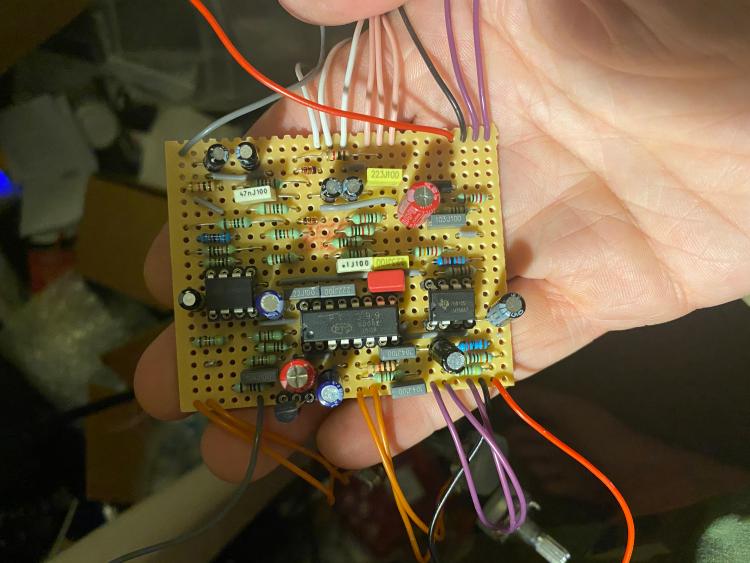
It appears Alex swapped IC3.1 and IC3.2 on the layout, so on the schematic what is shown as IC3.1 is actually IC3.2 and vice versa. So the pin numbering is also swapped. Layout matches schematic once you renumber everything for the LM358.

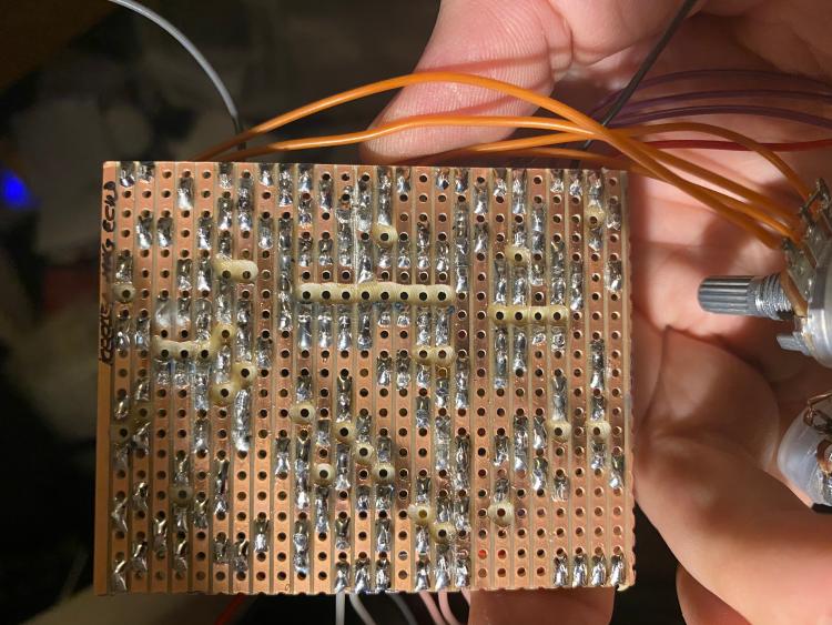
I suspect your issue lies with the parts connected to right hand side of the IC. I would suggest testing the seven resistors and two caps (R16,17,18,19,20,21 and 22 as well as C10 and C11). And maybe reflow the solder. Have you run a knife blade between rows?

Looking at the underside it appears you have the two links under the IC in the correct location.

On my build the LFO indicator is lit as long as there is power connected, weather bypassed or engaged. Well as long as it is not all the way CCW. The Speed pot should reflect a change in the rate the LED blinks.

Hope this helps some.