Alamondm wrote
I haven’t given up yet, let’s see if I get this one right, lol.
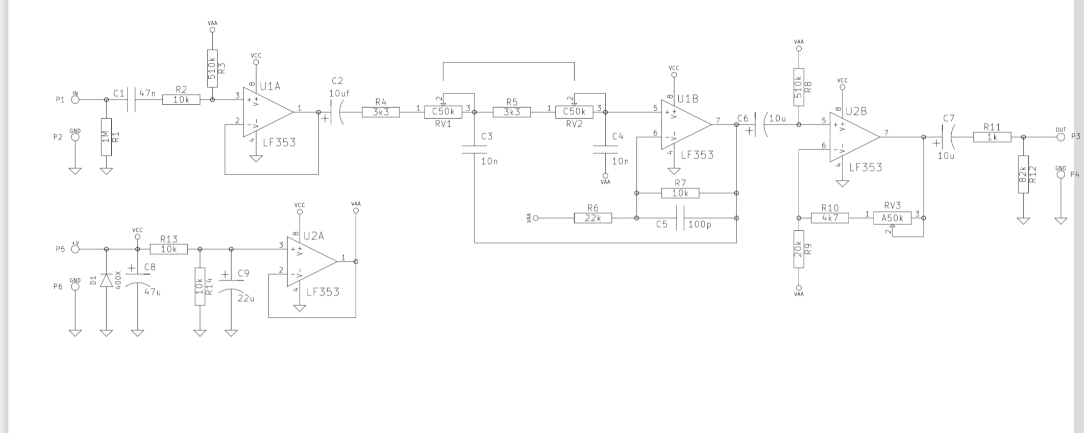
Leave pots at 50k
Make R4=1k, R5=1K, C3=10n, C4=15n , corner frequency sweep = 254Hz to 13Khz.
You got it. Good job.
In your opinion what do you think would be the best sweep for this. 500Hz to 5k maybe? That would also be useful for guitar as well?
When I'm building a circuit, the way I answer these types of questions is to build the circuit on a breadboard and experiment until I get what I want.
If I had to guess, I'd think the original sweep was probably good enough for both guitar and bass. So I'd approach it like this:
1. Build the original circuit on a breadboard. This would take maybe 5 minutes assuming I have all the components, which I do in this case, since there's nothing exotic in this circuit and I have a pretty big supply of components. (Breadboards are cheap and re-usable, so I'd advise buying one if you don't already have one and you plan on making more circuits in the future.)
2. Then I'd play through it for a while and use my ears to decide whether I wanted something from it that it wasn't giving me.
3. Then I'd start modifying the sweep and maybe the gain and/or pot tapers to explore what's possible with the circuit. I'd keep notes on what I find. I'd do this step whether I was happy with the circuit in step 2 or not, since this is how you grow your intuition on circuit design. Trust me, this part is 1000x easier on a breadboard than on a soldered pcb or vero. Along the way, you can explore whether having the extra range on the frequency sweep gives you extra options you actually want, or if it just makes the top half of the frequency pot sweep mostly useless, which makes it harder to fine-tune that parameter. Convenience vs. control is one of that balances that each designer has to figure out, and can be a highly personal decision. When you're building a commercial unit, you have to impose your choices on the user, which results in different decisions than if you're building for yourself. In the latter case, you can just make it exactly how you want it.
4. Once you decide exactly what you want to build, use the breadboard circuit in the context you plan to use the final circuit in for a little while to see if you change your mind about anything. What sounds powerful in isolation can often sound muddy in a live band, etc.
5. Once you make your final design choices, build it on vero or pcb or whatever, box it up and start using it.
This is the process I follow and I find it very useful. Others have different approaches that work well for them, so I don't want you to think that this is the one true path or anything. It's just what works for me.
Finally, about your specific question of the frequency sweep: EQ for guitar or bass usually has the frequency range limited to what's useful for that instrument. If you crank up the 15 kHz band on a distorted electric guitar and you'll mostly just hear an increase in hiss, so many guitar-specific EQs won't even give you the option. The same filter on a mix of several instruments including drums, keyboards, etc. where there is actually useful information in the 15 kHz band will have a different result. It's likely that the LPF kit you saw with a corner frequency sweep up to 22 kHz would be best applied to a full band mix or a synthesizer or something. Limiting that range would almost certainly make it more useful for guitar or bass or any other instrument that doesn't have useful fundamentals or overtones above 5 kHz. Different tools for different applications. But you can't be sure what you want until you try it out. Figuring this out is what step 3 above is for.