Lastgasp Art Laboratories (LAL) - Rattle Crow Resistive Filter

classic Classic list List threaded Threaded
6 messages Options
Reply | Threaded
Open this post in threaded view
|

Lastgasp Art Laboratories (LAL) - Rattle Crow Resistive Filter

notnews
This post was updated on .
Hey All,

So don't laugh too loudly. I found a schematic for the rattle crow and figured I'd take a stab at a layout... my first real try at a completed vero. Any feedback would be welcome, I'm sure that I've bungled something up. If my vero is just complete nonsense, I apologize!

Schematic:


Vero:


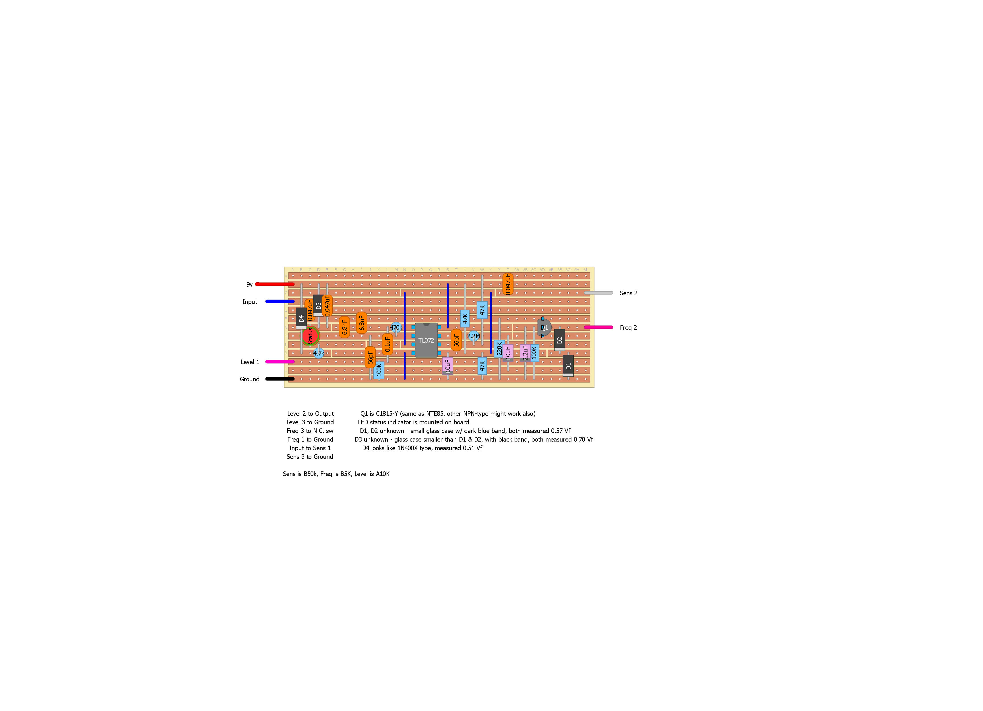
My first real contribution to the community.. I figured I'd make something I knew for sure didn't exist. Hope a few others are interested in this too.. it's a pretty interesting circuit for such few components and a pretty cool sound. Note that I just downloaded the DIY layout creator and don't very many component templates at all. Please excuse the crude appearance of the layout..

edit: just an FYI, the cuts are the beige vertical lines between holes, and the cuts underneath the IC just aren't showing thru the IC. I can probably mess with the opacity of the components, which I see is commonplace among the professionals... hoping the general jist of the logic of this layout is apparent despite the aesthetic
Reply | Threaded
Open this post in threaded view
|

Re: Lastgasp Art Laboratories (LAL) - Rattle Crow Resistive Filter

Neil mcNasty
Congratulations with starting something very addictive and time consuming.
Being able to do your own layouts is a very handy thing.

Absolutely no need for laughing here...
Looks like a good start!

Here's a couple of tips to start off with:

- Size: In your DIYLC application...
Go to the edit menu
Scroll down to the bottom where it says "edit document" and click it
Then set the document size (height and width) that you need for the layout.
At the moment you are using the default size that results in a lot of empty space

- Compactness:
As you probably can see, there are many components that can crammed together (slided sideways) and thereby take up less space.
Like: The bottom 100K fits nicely below the IC....
the 6.8nf caps can go tighter and one of them fits in-between the caps to the right.
The junction (where components meet/join) of the 47K and the 47nf (your 0.047uf) can be at the unused row E, instead of the top row and thereby reduce the height, and so on...
Apply this thinking/logic all over the board, and you will get rid of the un-necessary gaps, and the board gets drastically smaller.
Working with trace-cuts takes a while to get into, but is the secret to getting things as compact as possible.

Transparency:
Double click your IC and notice that at top of the dialog box that appears, there is a drawbar that sets the transparency of the components.

- Default symbols i DIYLC:
When you double-click your components to add the values, notice all the boxes to the right
If you tick off these boxes, you will then set the future default value for the selected box/section
Like: if like to change your trace cuts, you can do so by double-clicking the cut, then clicking off the "cut between holes" option in order to get the red box cuts instead, and if you then tick off the box on the right side, then it will make this option your default in the future... A very handy feature!

Enjoy

Reply | Threaded
Open this post in threaded view
|

Re: Lastgasp Art Laboratories (LAL) - Rattle Crow Resistive Filter

notnews
Neil thanks for the advice.
When you say trace cuts, you mean the trace cut lines in the layout I posted as opposed to the red squares that consume an entire hole in the strip, right? What is the best tool/way to do this to a real veroboard?
Reply | Threaded
Open this post in threaded view
|

Re: Lastgasp Art Laboratories (LAL) - Rattle Crow Resistive Filter

Neil mcNasty
Yes, I'm talking about the trace cut in the layout...

Most people use a small drill-bit to cut the traces (rotate a small dril-bit by hand, centered in the hole of where you want to cut)
....so from my understanding people then also prefer the red square cuts in the layout, as they take up the same space as your drill-bit cut will consume on the vero.

By double-clicking the cut (can be a bit difficult to hit), a dialog box appears, where you will find an option where you can de-select "cut between holes" ....then you'll have the red square cuts.
If you then also; select the box on it's far right side, you have then set this choice as your default setting for the future...

All components that you add to your layout has this feature, and by using these selection boxes ("make default" option) at the far right in the dialog box that appears when double-clicking a component, it makes a very nice way to customise your default settings, in order to speed up your workflow and standardise your layouts. A real timesaver!
Reply | Threaded
Open this post in threaded view
|

Re: Lastgasp Art Laboratories (LAL) - Rattle Crow Resistive Filter

notnews
I am familiar with using the drill bit to cut a circle (any shape rotated 360 degrees) in a track, I was hoping you knew of a tool that makes easier cutting a slit in the track, more aesthetically similar to the trace line cuts in this layout than the red squares that require sacrificing a hole. Does anyone actually cut their tracks with a thin line between holes like this?
Reply | Threaded
Open this post in threaded view
|

Re: Lastgasp Art Laboratories (LAL) - Rattle Crow Resistive Filter

Silver Blues
I do not. The hole method is the easiest and least time consuming. One could simply cut the portion of track with an Xacto knife and then pare away the unwanted piece to make cuts like the ones you're thinking of but this wouldn't be much of an advantage most of the time.
Through all the worry and pain we move on