Layout - Going into THE BOX


|
This post was updated on .
OK - I am a little beyond Noob, but not much. My question...
I have built maybe 6 of these now. Not one was perfect from the start, but I am getting faster & better and they are getting more complicated. My question.... when it comes to the the hard part for me - getting it in the box - what is the procedure, really? I see a lot of you place all the box external components in the box first: DC adapter, Jacks, pots, switches, LED, - and then you wire the ground... and finally you put in the circuit. My question is this - are you guys all actually so confident that your circuit is perfect that you do NOT wire up power and jacks to test it before it is mounted, not to mention pots & switches. All of my projects so far are mostly like spider webs with the circuit board in the middle and pots, switches, jacks & stuff hanging off - before it goes in an enclosure. But this makes mounting them in enclosures hard - because you have to move all the parts around and hope they all fit and that you didn't cross too many wires. Is is just my inexperience? Is it that when YOU look at a circuit it talks to you and says "Silly man, you cannot have that cap only one hole away from the resistor, it will not work that way" So, you just know if a circuit is right? My real question is this - if you lay out the foot switch, the LED, the jacks , the pots.... then wire all the grounds, and then wire the pots to the circuit, how to do get the wires from the pots into the right holes on the vero and solder them? Do you lift one side up and finish it off, then do the other side? While you are building it - do you have a permanent "workbench" with DC power, an audio feed, an amplifier, etc., all ready so you can test when the circuit looks right before you mount it? If so - how do you connect the temporary parts? The build guide on this site is like an "in a perfect world" scenario. But it goes from "I populate the enclosure" to "I add the circuit" and Bingo.... I'm done. I feel there must be a few additional details there. Do you all really wire the entire enclosure, then connect the circuit before its even been tested? |
|
Administrator
|
Everyone should always test the effect before they commit themselves to box. No matter how good and experienced they are, they have no control over a dodgy cap which will leave them needing to deconstruct everything if they haven't tested first.
This is what I do: 1) Solder up the board completely and leave trailing wires for all connections including pots, input, outputs, supply and ground (and anything I missed  ). Also mount the input and output jacks, stomp switch and DC adapter in the box so that is out of the way. ). Also mount the input and output jacks, stomp switch and DC adapter in the box so that is out of the way.
2) Push all required pots in a breadboard so you can test them before committing to solder. I use mostly PCB pin pots but even if I was using the ones with the solder lugs I would still test the effect with pin pots just so I can make the temporary connection on a breadboard. 3) Connect input, output, supply, and ground wires to a terminal block so I can make a temporary connection to test. Because I won't wire up the stomp before testing to avoid another potential point of failure I use a terminal block to connect the input wire from the board to the input socket, and the same for the output. As shown here: 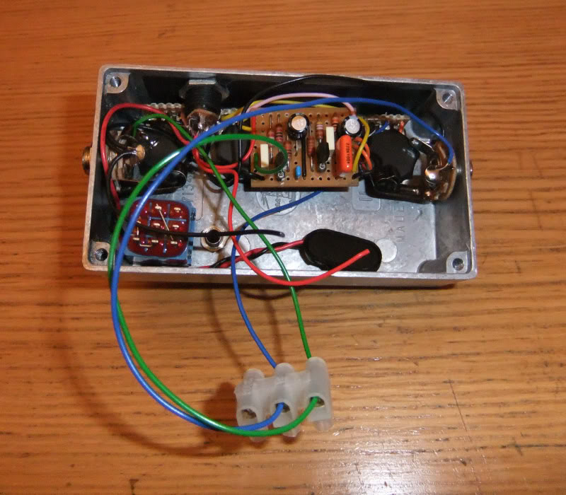 I will use a similar block to connect supply to the board and also to common all grounds together. I also use a block like this to make the pot connections from the soldered wires, using solid wire the other side of the terminal block so I can push them in the breadboard to test the pots mounted earlier. 4) Once that is all connected up test away. Don't expect anything perfect, especially using a breadboard to make some of the connections. I often get oscillation when testing but that doesn't matter, it still allows you to check the circuit works as intended and the pots behave as expect in the correct rotation. When boxing is complete any oscillation is almost always removed completely by the shielding provided by the grounded box. 5) Assuming everything works as intended, disconnect all the test stuff and prepare to mount it all in your box. 6) To box (with stomp, input, output, DC sockets already installed) I mount the pots first, put the board in they're approximate orientation and then estimate the pot wire length required by bending them approximately to where they are going to connect. Then snip them all to length (+ a little bit extra). I usually then remove the pots from the box and solder them away from the box so I have plenty of space. Once all the wires are connected I'll again mount them in the box and tighten them up, putting the board in its expected position (usually sat on the back of the pots). 7) This only leaves the input, output, supply and ground wires. It should be easy enough to put them in position down the appropriate side of the box and you can then measure, snip and solder into place. I solder the stomp as per the Offboard diagram on the blog, and I always solder the link before mounting it in the box, but only one side, leaving the other side where the input jack wire connects unsoldered so it can be done in situ when connecting the input wire. You may have a few ground connections to make, I usually use one or both of the input and output sockets because they are big and sturdy and can take plenty of heat without damaging. The only thing I have omitted here is the LED because you may do it a number of ways (offboard on floating wires, stomp daughterboards etc etc) and so you'll have to choose the method that best suits you. By far my favourite LED method to simplify it offboard is a 3PDT daughterboard where the LED connection and current limiting resistor is included. This allows you to mount the 3PDT soldered up with the LED pushed through the holes but not yet soldered. Then you can just push it through the LED hole drilled in the box and solder it in place without even having to use any bezels, the daughterboard holds it into place sturdily enough and it's a real time saver. If you do use a daughterboard with a current limiting resistor for the LED, then you can of course omit the CLR on the board and the LED+ wire for those layouts where I included one. And that's it. Rock out  It may seem time consuming and complicated with those steps and suggestions but once you get your own routine going you will do the offboard in no time especially if you make up your own test box or board where all the required terminals are already in place ready to make the process even quicker. It is still the most annoying part of a build though
|
|
|
Thank you - you really did an excellent job answering this question. I think it should be a sticky or possibly a blog post. Pictures of the terminal blocks and maybe a few "action pics" taken during the process of connecting the pots would really add, too.
Once again, just THANK YOU so much for all the effort and attention to detail you guys offer with this site. It is extraordinary. I have to say it was far from the first site I found, probably one of the last of about 40 sites, but once I got started here I never really left. It is the only all Vero site that I have found (other than a blog or two) and Vero is not widely accepted, but it seems very stable to me. If you etch a PCB there can be errors, and even when they are right there is no artistry in making the pedal according to someone else's design (paint by numbers). I still have a lot to learn, but I have also made some extraordinary sounding circuits from what I have found here. One thing that is funny is that I did become well stocked in parts right away - because you soon realize everything is cheaper by the dozen, and that it makes the whole thing a lot more fun when you have the parts you need. I still get thrown by an odd IC or Transistor request once in awhile, and I have way more LEDs than I need. But still, it's too much fun. |
|
|
In reply to this post by IvIark
Love it! I learned a few tricks reading this! One point of interest - you mentioned a daughter board for the LED and resistor. Is there an example of this that you can point me to please?
Yeah, 220, 221. Whatever it takes.
|
|
|
I don't think it is anything special - just a small piece of vero so you can clip the long LED leads and also put the resistor right next to it, so it is one combined unit. This actually makes sense since when I was looking at the layout guide I could not see a CLR (current limiting Resistor) anywhere between the foot switch and the LED, so it makes sense that it is somewhat hidden from you on a small piece of vero.
They usually put the LED in the same place each time, right above the foot switch - which is OK unless you step on it and push it in ;-) I bought a bunch of 3mm LED sockets - but he was saying he just pushes them through the case - but he did not say how he fastens them in there (I have used white glue before - not that I recommend it, but it works if the hole is tight enough) |
|
Administrator
|
In reply to this post by Chris60601
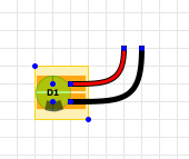
If I'm mounting the LED with flying leads from the board I always use a little piece of vero to mount the LED, basically because I really hate soldering wires to pins. Like this
 But what I meant above is using a daughterboard for the stomp switch with a built in CLR and LED connection, like these ones I recently bought from OSH Parks https://oshpark.com/shared_projects/HbIVe0kT It just takes one of the offboard pains away, and having multiple ground pads is very useful to connect all your grounds up |
«
Return to Open Chat
|
1 view|%1 views
| Free forum by Nabble | Edit this page |