mug81 wrote
as bsas wrote one circuit should connect the tips and one the rings of in/output, so it filters both ground and signal wire!
Not quite. It's designed for both stereo and mono signals. When a stereo cable is used, it will filter DC off of both the left and right signal path. When a mono cable is used, both sides of the caps connected to the ring are grounded, so they are removed from the circuit and don't do anything. If your rig is all mono, the second filter is not necessary.
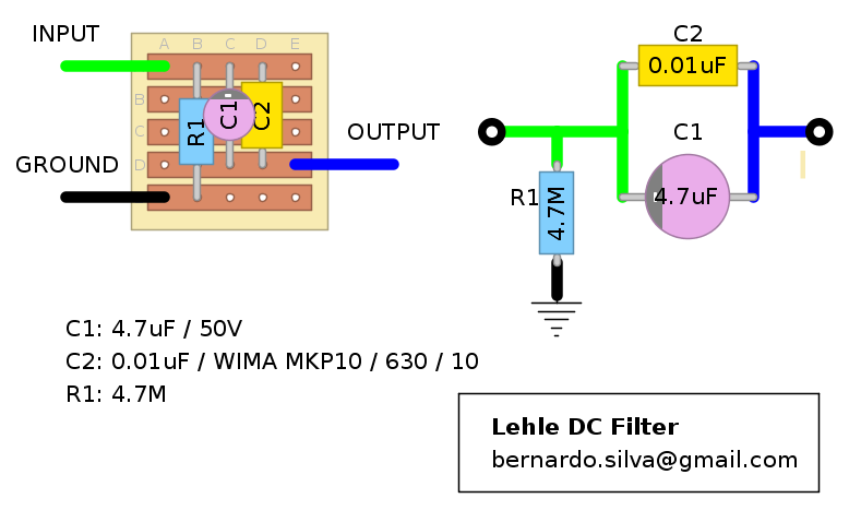
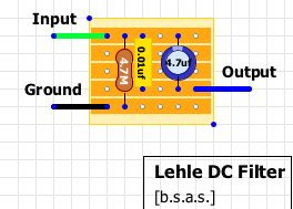
Another quibble: The vero says that one wire is for input, and the other is for output. This isn't quite correct either. One of the filter's jacks (labeled 'DC' in the original unit - the most misleading label I've ever seen on a jack - it's the side connected to the positive leg of the electro without the pulldown resistor) connects to whatever equipment has DC voltage on it's own (input or output) jack. The other filter jack (labeled '0DC' in the original unit, it's the side attached to the pulldown resistor) connects to the input or output jack of the next or previous circuit in your chain. The labeling difference might seem like a small detail, but it's actually fairly important, for reasons that will be made clear in the following paragraphs.
The filter is for eliminating pops (it's just a coupling cap and a pulldown resistor in a box) that come from equipment with DC on one of the jacks. It's good for equipment that you don't want to modify. If I had a pedal or amp that leaked DC, I'd just replace the leaky input or output cap (or install the missing input or output cap inside the unit itself), especially if the circuit in question was one I built myself. But I can understand not wanting to mod a commercial amp or pedal.
A couple of things to consider. This unit is only designed to cure pops from DC voltage on a switched jack. That's all it does. It doesn't cure pops that come from DC on the circuit board input or output, and it doesn't filter any other noise or hiss or anything. If you don't have DC on one of your jacks, you should not use it. Here's why: In order to pass the full frequency range of audio signals, it uses an electro and a film coupling cap in parallel. The electro expects to see a DC bias across it. If it doesn't, then half of the signal will reverse bias the cap, which will shorten its life, eventually causing it to fail. When it fails, it will turn into a short circuit, which will defeat the film cap as well. Nothing terrible will happen, the filter will just turn into a box with a wire inside. But it will no longer work if you try to use it for it's intended application, should you decide to move it to a jack that is actually leaking DC.
The worst case is to use it backwards. If you attach the '0DC' jack to the circuit with a positive DC offset and attach the 'DC' jack to the circuit without a positive DC offset, you will kill the electro very quickly. Again, that will probably just defeat the circuit, turning it into a wire in a box. It shouldn't explode or steal your silverware or anything, but the switching pops will come back. The design can be made more robust by using a non-polar electro (or two polar electros, each with the same value as the original, in series with their negative legs tied together) instead of the polar electro. The pulldown should still go on the side without the DC offset, so it still won't be perfectly reversible. (Really, the side the pulldown is on isn't that big of a deal. If the DC on the jack is high enough to cause significant current through the pulldown, you should get the unit repaired before it kills you.)
It will probably help for pops that come from switching an FX loop on and off or from an amp switcher (because there may be DC on one of the loop jacks or amp inputs), but it often won't help so much for switching individual pedals, whether in the FX loop or in front of the amp. Usually, those pops are caused by DC on the circuit board input or output, not on the jack. Putting an extra coupling cap between your pedals won't get rid of stray DC on the circuit board while in bypass. It
will help for cases of what Mark Hammer calls 'pedal ventriloquism', where a pedal with buffered bypass leaks DC into a neighboring true bypass pedal, causing the TB pedal to pop when switched. But again, you can also just fix the pedal that leaks DC instead.
To use the filter correctly, you have to know which jack has DC on it. You should measure the DC with a DMM so you don't reverse the filter, and you should make sure the DC offset is positive. With a bipolar supply or a negative ground pedal, the offset voltage could be negative, in which case you should reverse the filter, though the pulldown will still be on the wrong side. In this case, assuming you don't want to mod or repair the offending circuit, I'd build either a negative DC filter, with the pulldown on the other side, or just use a non-polar electro.
That was an awful lot of writing for a circuit that's just a couple of caps and a resistor in a box. But if you haven't had your fill, you can always download the
user manual.