Locations for Mods Question


Administrator
|
got a question. i'm looking at working on making some modifications to some pedals to change some of their properties and i'm not sure where i should be looking to get my desired results. for example:
1 - if i want to raise the amount of gain in an overdrive/fuzz, my understanding is that i want to change the resistance from the emitter of the transistor in the gain stage to ground, and conversely if i want to lower the amount of gain i would lower the same resistor. 2 - if i want to change the frequency response i want to look at the hpf/lpf which should be near the tone control and change either the cap or resistor. 3 - to increase/decrease the frequencies that pass into/out of the circuit i want to look at the input & output caps, as well as coupling caps (connect one stage to another, ie: look for cap between 2 transistors). so if i take the beebaa circuit i marked locations and labeled the changes i would expect from altering these components. 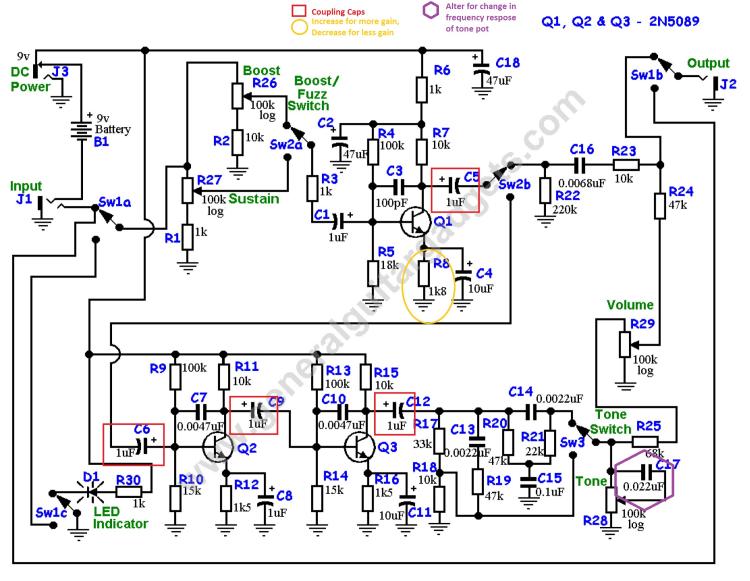 am i looking in the correct areas? |
|
|
Looks fine. Just a note about that emitter resistor - lower value = more gain
|
|
|
That beebaa schematic includes the boost portion, which is fine, but it's in that section that you're modding the gain (instead of the fuzz section).
The lower array of cascading transistors is where you would play with the emitter resistors if you're wanting to adjust the fuzz section.
Q: Why is a drummer like a scud missile?
A: Both are offensive and inaccurate. |
|
|
The gain stages in that schematic include emitter bypass caps, which means that the emitter resistors are controlling the dc gain (ie the bias point), but not the ac gain (ie the signal gain). You can increase the ac gain by increasing the collector resistor, but you'll have to adjust the emitter resistor as well in order to maintain the correct bias.
In more detail: The DC voltage gain is RC/(Re+re), where Rc is the collector resistor, Re is the emitter resistor, and re is the effective resistance of the transistor. The AC voltage gain is Rc/re, because the emitter resistor is bypassed to AC signals by the parallel capacitor. (I'm ignoring the feedback cap here.) So, to increase ac gain and maintain dc bias, increase Rc to taste, but set Re ~= Rc*1.5/10. (We can ignore re for biasing purposes because re is small enough that Rc/(Re+re) ~= Rc/Re). Read this and this for a more complete understanding. |
|
Administrator
|
This post was updated on .
As always thanks guys of the help.
I didn't realize that the transistor at the top of the schematic was part of the boost. When I was reading the schematic to find the different stages I was looking at the different control pots, so I assumed that the transistor in the fuzz stage was near the sustain control. With that being said, to alter the gain I would want to change the resistor/cap on just q2, just q3, or both? Induction, thanks for the suggested reading, always can use more information so I don't have to ask potentially obvious questions. Any suggestions for reading pedal schematics in particular, to better understand how to identify parts of the circuit based on what they would do? Also, i would assume that the same rule apply if altering the emitter resistor, lower=more gain. I know that I have to experiment to get it right, but if I lowered Rc, would I expect Re to need to be lowered for bias purposes to or would it need to increase? Tj, I actually meant to say that lowering the resistor would increase gain, but I guess my fingers didn't get the memo. |
|
|
The rule of thumb (lower emitter resistor = more gain) comes from the ac gain equation for the common emitter amplifier: gain = Rc/(Re+re) ~= Rc/Re (same as the dc gain equation). Decrease Re, gain goes up. Increase Rc, gain goes up.
When there is an emitter bypass cap, the dc gain equation stays the same, but Re is removed from the ac gain equation. Now ac gain = Rc/re, so the rule of thumb no longer applies. The gain is now controlled by Rc. Lowering Re won't increase the gain, it will just change the dc bias point. So we use Rc to select the gain, then use Re to maintain the bias point. To keep the biasing the same, we want to keep Rc/Re the same. So if we lower Rc (to lower the gain) we have to lower Re as well. If we increase Rc (to increase the gain) we have to increase Re as well. In either case you can use: Re_new = Rc_new*Re_old/Rc_old. In this case, that works out to about Re_new = Rc_new*0.15. As for reading schematics, it's mostly about experience with building blocks. This circuit is essentially three common emitter amplifiers in a row followed by a tone network. Look up the LPB-1 schematic, and then find the three nearly identical versions of it in this schematic. Then look up the Cot-50 (aka electra) schematic, and the rangemaster, and the Vox Treble Booster. Compare and contrast them. They are all common emitter amplifiers with slight differences (biasing, gain, clipping, input/output caps). In boost mode, this circuit is just one common emitter amplifier, similar to the LPB-1 with some mods. In fuzz mode, it adds two more common emitter amplifiers in series with the first. (Cascading gain stages like this is one of the common ways of making distortion.) Now find a Tonebender mkII schematic and tell me what you see. Now find a Fuzz Face schematic and tell me what you see. The common emitter amplifier is a building block you'll find over and over in pedal circuits. I'm guessing that you'll get more saturation by increasing the gain of Q2, and more volume by increasing the gain of Q3. But this circuit is pretty saturated already, so you might just get more saturation either way. If you boost the gain of Q1 instead, you'll get a louder boost in boost mode, and more saturation in fuzz mode. The general rule is: boost the input for more distortion (because the output of a gain stage is more likely to hit the rails when the input is bigger, and trying to exceed the rail voltages generates clipping) and boost the output for more volume. If the output is already hitting the rails, boosting the output only adds more distortion. Whether boosting the gain of any of these stages improves the sound is something you'll have to test for yourself. It might just get muddier, I don't really know. I haven't tried it. Hope this helps. |
|
Administrator
|
awesome induction, some how that all makes a lot of sense. so then if i understand the schematic right the sustain control controls the fuzz level by acting like a pre-gain (dumping input voltage to ground so you're not slamming the first stage), right? and if that's right, the second gain stage of the fuzz section is really a recovery stage to bring the volume back up and/or boost the output. Which is similar to the BMP, but that has 4 gain stages total, right? but, now what confuses me then is how different controls are added. like active tone controls (bass, treble, mids), fuzz control, etc.
the more i dive into circuit designs it really seems that its just the same few circuits put together in different ways, and changing some values, and you end up with something new. |
|
|
You're right, the sustain controls dumps some of the input signal to ground so that the first boost stage won't boost so hard, but for most useable settings of the sustain pot, the first stage will be a boost not a cut. The second stage isn't makeup gain, it's cascaded boost for adding distortion. Feeding a boosted signal to a boost stage creates clipping (ie distortion). In fuzz mode, this circuit boosts the signal three times, each time adds clipping. Clipping the signal in three successive stages instead of just using one boost with three times the gain gives a more complex sounding distortion. Tone controls are usually accomplished by selectively dumping certain frequencies to ground. For example, a hi-pass filter feeds the signal to a cap, then to a resistor to ground. The output is taken from the junction of the cap and the resistor. A cap can be thought of as a resistor that has more resistance (technically called 'capacitive reactance') to lower frequencies than high ones. The value of the capacitive reactance is Xc = 1/(2*pi*f*C) (ignoring phase), where f is the frequency and C is the capacitance. The hi-pass filter, then, is just a frequency-dependent voltage divider, Vout = Vin*R/(R+1/2*pi*f*C). As f increases, this gets closer to Vout = Vin. As f decreases, this gets closer to Vout = 0. Thus, high frequencies are retained, and low frequencies are dumped to ground. A guitar tone pot is also a hi-pass filter with a cap and a variable resistor, but the configuration is a little different. A low-pass filter simply reverses the order of the cap and the resistor, so now Vout = Vin/(1+2*pi*f*C*R). As f increases, this gets closer to Vout = 0. As f decreases, this gets closer to Vout = Vin. So, low frequencies are retained and high frequencies are dumped to ground. Hi-pass and low-pass filters are 'passive' filters, which means that they operate by dropping unwanted signal, so the overall signal gets quieter. If the signal going into them is already too loud, then the output might be just right, volume-wise. Otherwise they will need to be boosted afterward by a make-up stage. You mentioned the BMP, which is a very good comparison. Put the bee-baa schematic and the BMP schematic next to each other, and you'll see that they have almost the same topology, but the BMP puts a make-up gain stage (another common emitter) after the tone control, and before the volume control. The tone control that's used in the BMP is extremely lossy, so the make-up stage is necessary to get unity gain out of the circuit as a whole. (The BMP also has clipping diodes incorporated into some of the gain stages, so the character of the distortion is a little different, and the tone control is very scooped, so the frequency response is different). The component values may change, but the topology is almost exactly the same except for that make-up stage and the type of tone control. Passive filters operate on selective use of resistance and capacitance, so they behave very differently depending on what surrounds them. The output impedance of whatever stage precedes them and the input impedance of whatever follows them can have a drastic effect on how they work. There are also 'active' filters, which means they can selectively boost frequencies as well as cut them. They require a gain device (transistor, op-amp, tube, etc.) to provide the boost, which is just a little bit different than providing pre or post gain to a passive filter. You can put these filters at various places within a circuit and they will have a different effect. Much of the work in designing distortion circuits is figuring out where to put the filters and how to tune them to give the distortion the flavor you want it to have. Fuzz and distortion controls are often either pre-gain controls like the one in the bee-baa (ie they control how much signal is available to be amplified), or else they control the actual gain of a boost stage (like using a pot as a variable emitter resistor in the fuzz face or electra, or in the feedback loop of an op-amp in the tube screamer). That's definitely true, and many or most boutique pedal and amp builders make their livings tweaking component values in time-tested circuits. But even very small changes to the circuit topology can make very large differences in the result. For example, look at the fuzz face and the tonebender mkII schematics. See the resistor that goes from the emitter of the last transistor to the base of the one preceding it? That one component has a huge effect on the operation of the circuit. Read this if you're interested in the details. Wow. That was a long post. |
|
Administrator
|
Man induction that was a crazy long post, but provided a ton a information that is beyond valuable and is a huge help. I swear between your help and some things r.g., and Paul over at diiysb forum, I feel like I'm being taught by Jedi masters. Lol.
The more I find out the more everything clicks. I'm getting more and more confident with moding my effects where I know what I'm doing rather then just trying random things because someone said to try "_" cap or resistor in place of another. The one thing you said that I don't get is how the fuzz control works on something like the fuzz face. I get the first transistor boosts the signal to drive transistor 2 into clipping, the pot goes from E to ground. How does that change the total fuzz? In my head it seems like its similar to the volume control, and would control the output. I think I'm just trying to over simplify it and making a poor conclusion based on something stupid I'm missing. |
|
|
Transistor clipping occurs when you try to boost a signal above the available voltage. Say you have an input that goes from -50mV to +50mV. After you send it through a common emitter stage with a gain of 2 that rebiases the output to 4.5V. The output signal now goes from 4.4mV to 4.6mV. This won't cause clipping. If the gain is 100, though, the output will go from -0.5V to 9.5V, but the power rails are 0V and 9V, and the output can't go outside these bounds. Any voltage less than 0V gets returned as 0V, and any voltage greater than 9V gets returned as 9V. This is clipping. (Though in practice, clipping usually occurs before the rails are reached.) Look at this for an illustration.
You can get clipping from a single stage by feeding a large signal to a modest boost, or by feeding a small signal to a huge boost. Either way, the output swing is wider than the rails, and can't be reproduced with the available voltage. Of course, you can also feed a huge signal to a huge boost to get even more clipping. This is easy with multiple stages. The first stage generates a loud signal that may or may not clip on its own. This signal is fed to a second stage that boosts it again: large input + high boost = lots of clipping. This is very similar to what the fuzz face does (even though that feedback resistor that complicates things a little, the broad strokes are the same). Q1 boosts the input signal, and Q2 boosts it again. The output tries to exceed the rail voltages and is clipped. The fuzz control puts a cap in parallel with the emitter resistor of Q2. For DC purposes, the emitter resistor is constant, so the biasing is constant. As you turn up the fuzz control, that resistor is increasingly bypassed to ac, so the ac gain increases, providing more and more clipping. Thanks for the comparison to R.G. and Paul, but rest assured, those guys are light years beyond me. |
|
Administrator
|
Awesome. As always, I can never thank you enough for all the help. While they may be light years ahead of you in knowledge, you always there to help and have just the right information, and have something to read to help. Not to mention I was always told a truly wise man not only knows sop,etching, but knows where to find what they don't know.

|
«
Return to Open Chat
|
1 view|%1 views
| Free forum by Nabble | Edit this page |