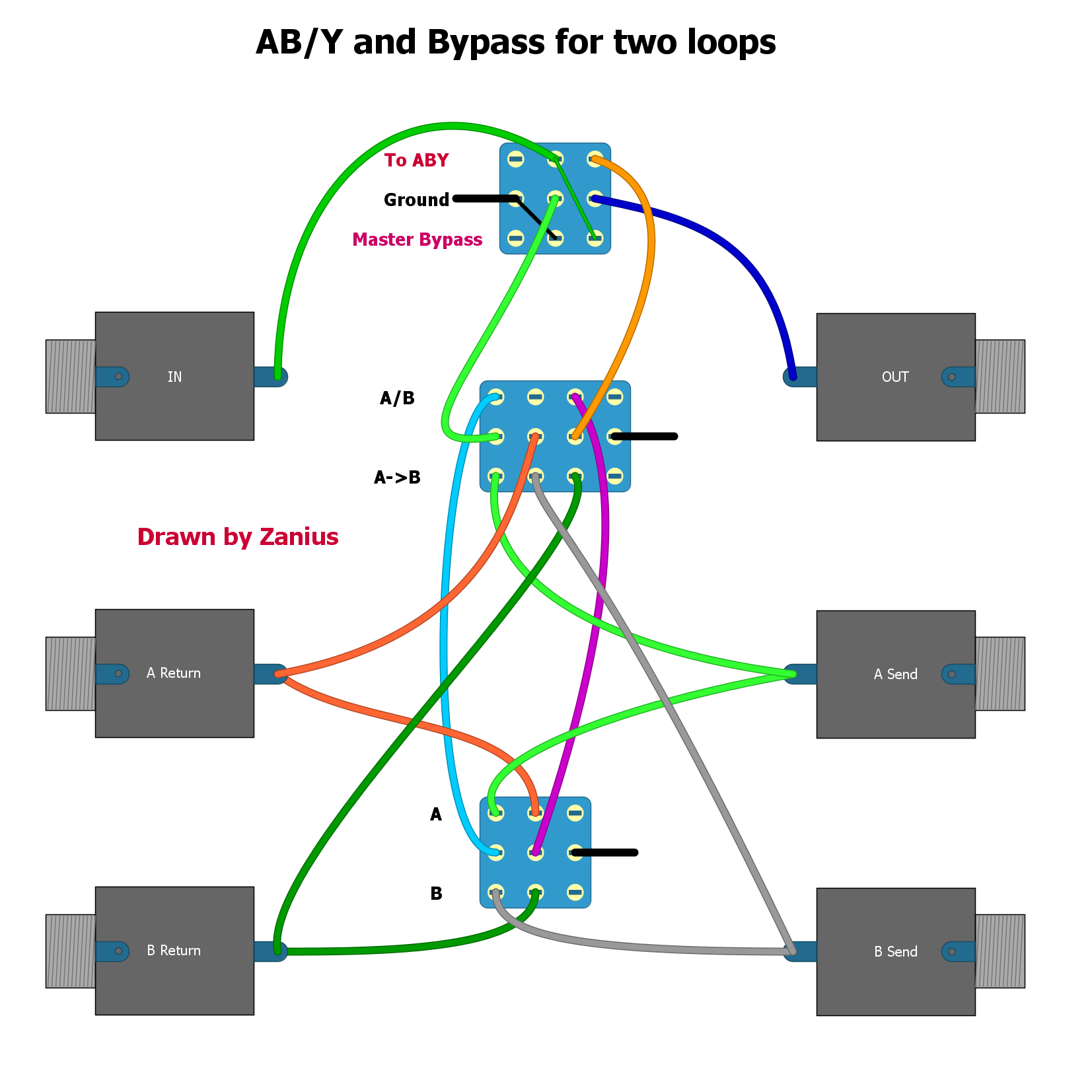
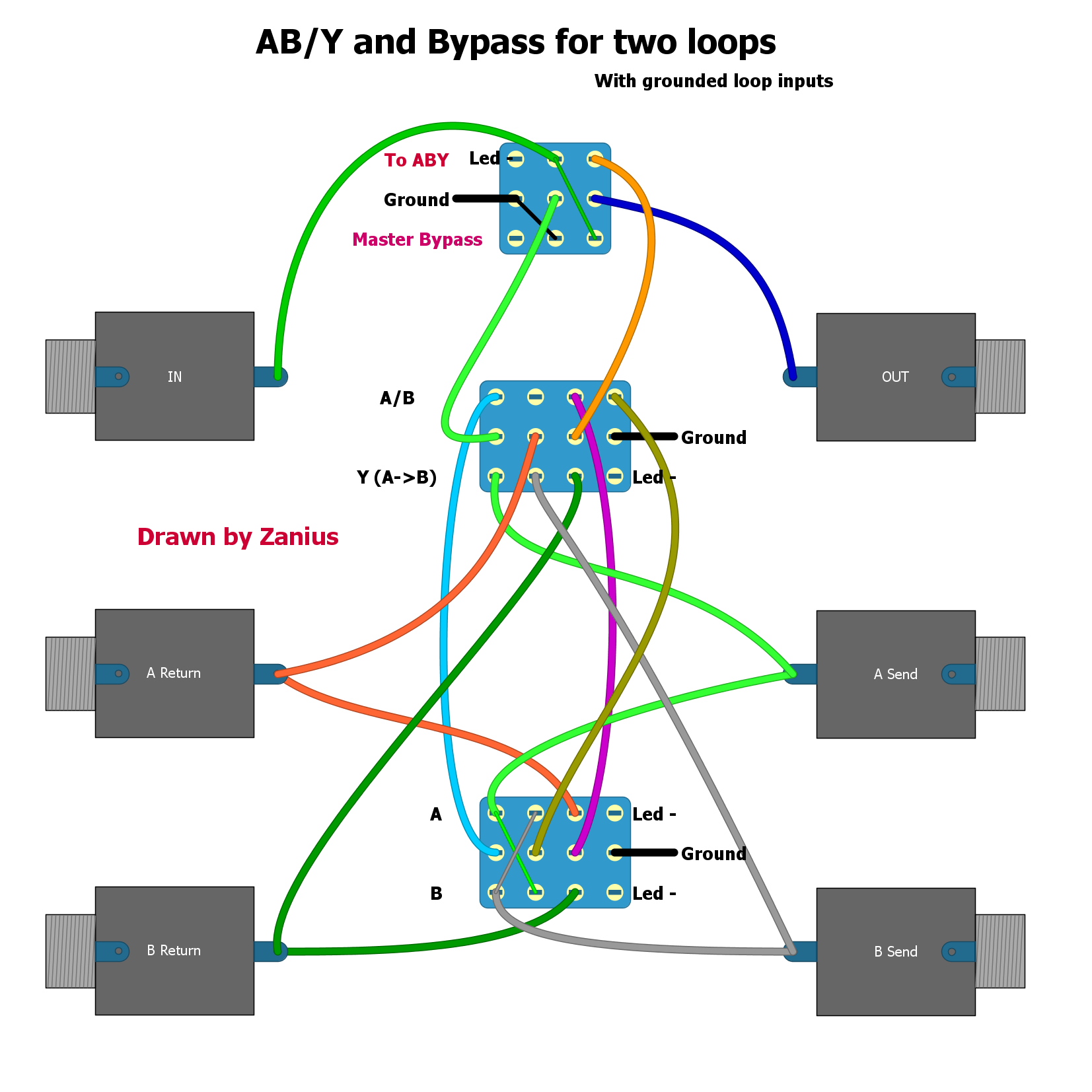
Oh boy, do I love figuring out how to wire switches to reroute stuff

Not very beutified, but here goes.
*******NOT TESTED*********
Let me say that seeing this, I would strongly recoment at least one buffer on the input and shielded cables for at least input and output. That is for the builder to decide of course. Some floating inputs and outputs there that I don't really like but I think it's the only way to make this happen with mechanical switching.
Now,
First diagram shows wiring WITHOUT grounding of loops inputs when not in use. That may as well work but poping may occure when switching between A B or Y.

At first I thought it would be tough to implement input grounding on this concept but I did it like this: Ground connects to the A/B switch inputs only when the other switch is in A/B position. Extra ground provided to the switch for constant led function though. And with of course another 4PDT switch :)

Sorry for huge images, you can always right click and "open image in new tab" for better viewing.