Lumpy's Lemon Drop with Pre-gain

12

12
Re: Lumpy's Lemon Drop with Pre-gain

|
Re: Lumpy's Lemon Drop with Pre-gain
|
|
Re: Lumpy's Lemon Drop with Pre-gain
|
|
Re: Lumpy's Lemon Drop with Pre-gain
|
|
Re: Lumpy's Lemon Drop with Pre-gain
|
|
Re: Lumpy's Lemon Drop with Pre-gain
|
|

Re: Lumpy's Lemon Drop with Pre-gain
|
|
Re: Lumpy's Lemon Drop with Pre-gain
|
|
Re: Lumpy's Lemon Drop with Pre-gain
|
|
Re: Lumpy's Lemon Drop with Pre-gain
|
|
Re: Lumpy's Lemon Drop with Pre-gain
|
|
Re: Lumpy's Lemon Drop with Pre-gain
|
|
Re: Lumpy's Lemon Drop with Pre-gain
|
|
Re: Lumpy's Lemon Drop with Pre-gain
|
|
Re: Lumpy's Lemon Drop with Pre-gain
|
|
Re: Lumpy's Lemon Drop with Pre-gain
|
|
Re: Lumpy's Lemon Drop with Pre-gain
|
|
Re: Lumpy's Lemon Drop with Pre-gain
|
|
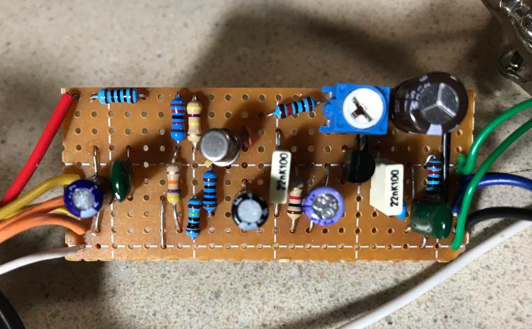
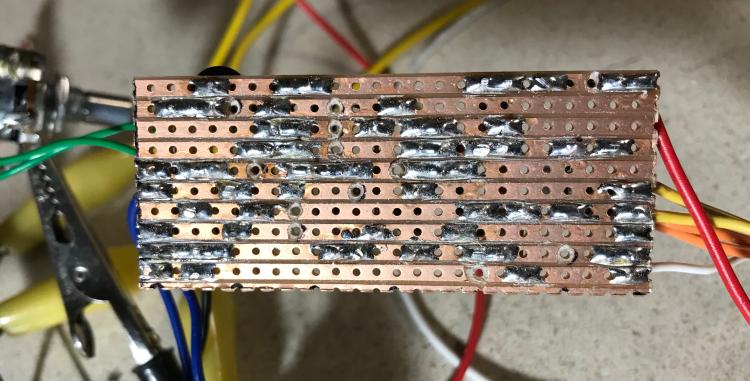
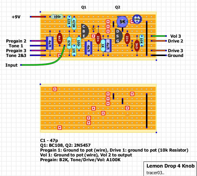
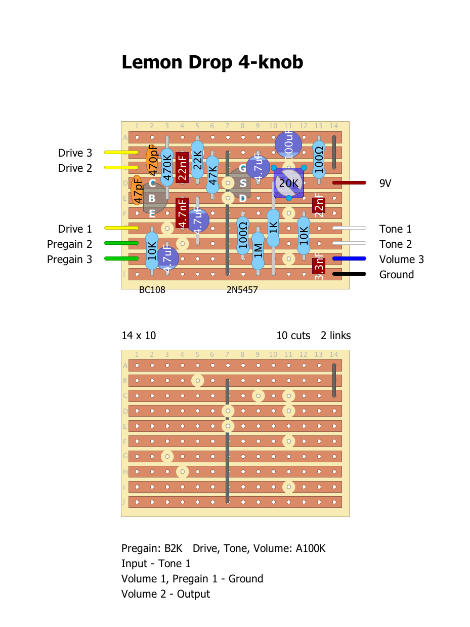
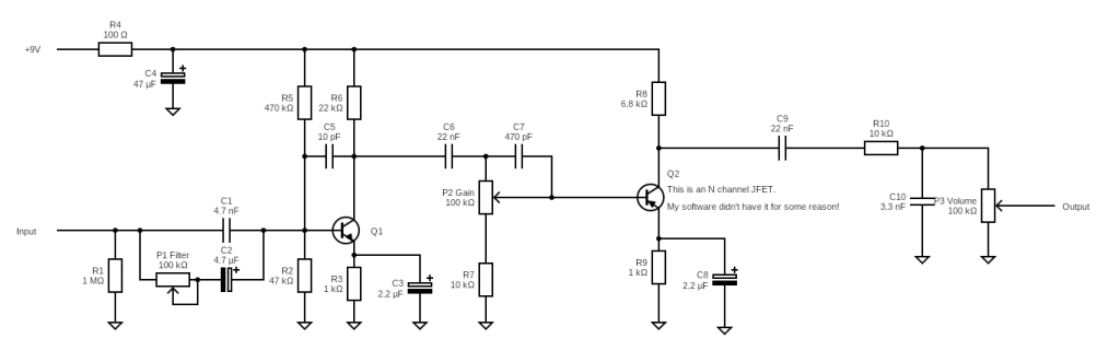 Can someone modify a schematic for the four knob version of this pedal like, where would I put that pregain knob..
| Free forum by Nabble | Edit this page |