MXR El Grande Bass Fuzz
12
12
|
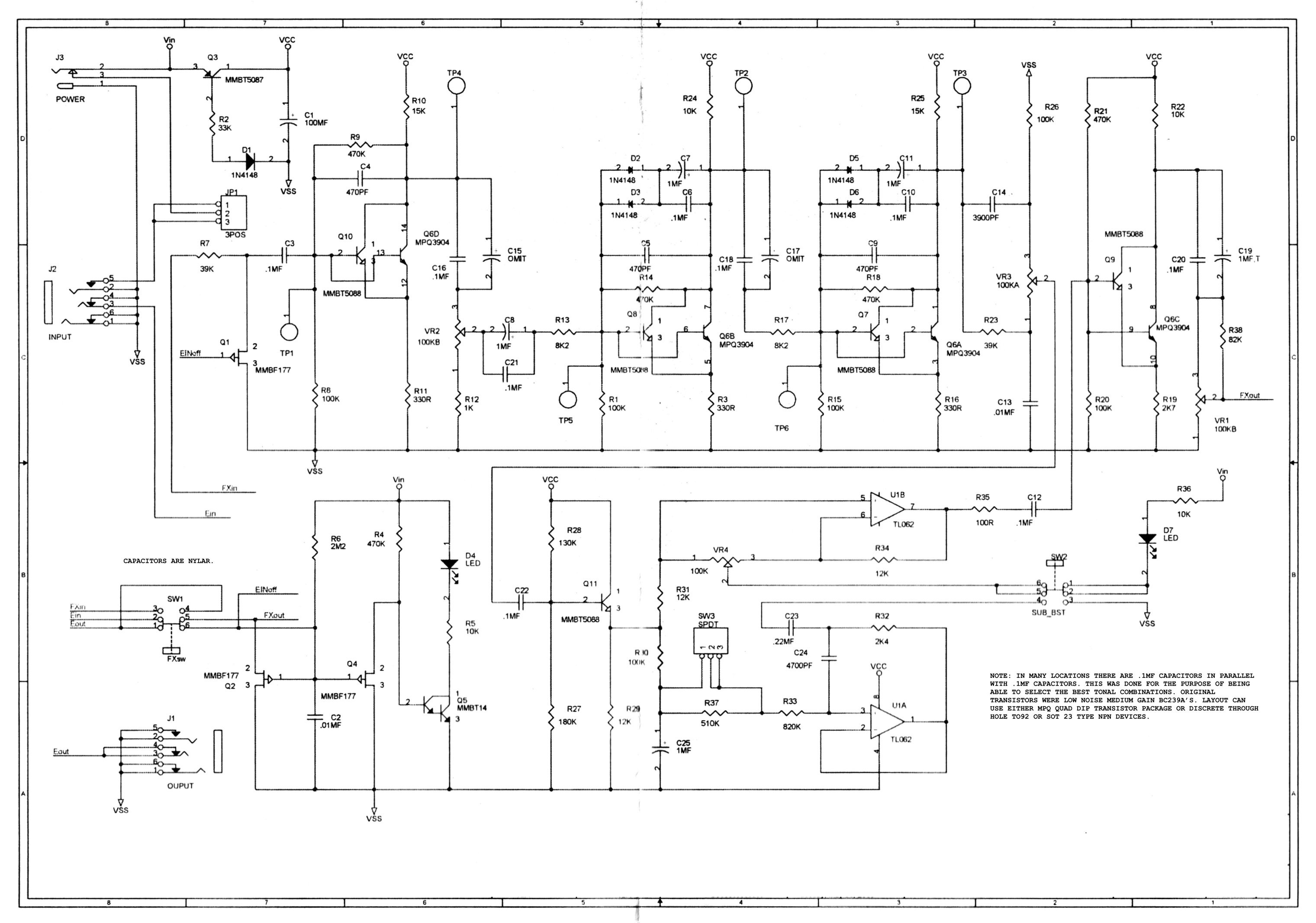
I have search and can not find a vero layout anywhere. Anybody care to take a try at it? Sorry about the size.

|
|
It seems very nice. It's a Big Muff variation with a thing I never seen: there's a couple of transistors at any stage connected each other. Why? What's change?
Then it has a sort internal mid bass control that can work at two difference frequency thank the external switch. I really think that is a good idea have boost/cut control outside. Maybe we can start to draw a layout from a stock Big Muff layout.
I build pedals
|
|
This post was updated on .
(Sorry, I thought I answered yet.
 I write again the post.) I write again the post.)
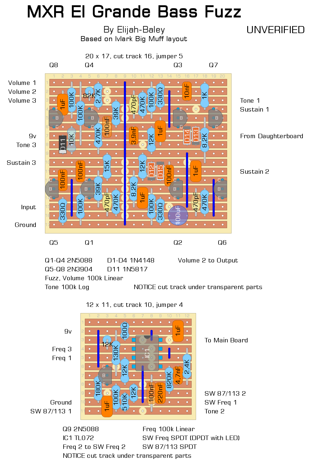
I tried to draw this solution: a modified version of the IvIark Big Muff layout (bigger with extra components and adjusted values) with a daughterboard for the extra section. I simplified the power supply and the switching sections. I forgot the name of the Deep switch and I called it Freq.  The internal trimmer is the external pot Freq. The internal trimmer is the external pot Freq.
I think the layout is clear enough, else ask me clarification. And tell me if you see some mistake. It's UNVERIFIED. Update: The layout has corrected, it sounds, but it could have still something wrong. 
I build pedals
|
|
Thank you for doing this. I’m not good enough yet to be able to pick out mistakes. I will build it and see what happens, lol. Could be a very cool bass fuzz.
|
|
Ok. I finally got some parts and time to work on this. I will do my best to explain what Ive found.The muff part seems to be working good. Nice and girthy muff. I may just use it without the daughter board.
The freq switch and the 87/113 switch seem to be working. You can hear a difference when switching the 87/113 switch. The Freq switch turns the freq on and off. Now heres where it gets odd. . When you turn the freq pot in gets all squally and you can hear the frequency of the squall changing, if you turn the tone pot you can somewhat dial it in to a usable fuzz. If you change the 87/113 switch you need to dial in the frequency with the tone pot. so I guess in summary what Im trying to say is if you play with the tone pot and the frequency pot you can dial in the fuzz to the frequncy. Make sense? I am a noob at this with minimal understanding of how things work. Im trying to learn more. Thank you for taking the time to do this layout. Im sure it was challenging. Cheers Matt |
|
Unfortunately, I don't know this pedal, and the original has the Frequency pot (that control the boost and cut, if I remember well) and the 87/113 switch that select one of the frequency, both inside the box on the PCB. So the trick in the original pedal is set the frequency and the boost as you wish, then close the box and forget.
Maybe, as you told us, this is not made to work fine without to adjust the pots every time you change the setting of the "extra" switch and the pot. But maybe this can makes the pedal more versatile, anyway. This are just my assumptions. I'll check my the daughter-board of my layout, to be sure there's no mistake and I'll do some emulation with my software trying to get what happend to the frequency, though I don't know what really happen to the sound: you called it squally, what you mean?
I build pedals
|
|
I guess the best way to describe squally would be it sounds like a tone generator sending a tone kind of like a long beep or whistle of sorts. When you turn the freq pot it changes th pitch. In the very bottom and top of the freq pot rotation you don’t hear the tone , it is mixed with the fuzz but in between those 2 points you hear the tone and no fuzz. I wish I could describe better. Thank you for all your effort.
|
|
Try to flip out the transistor of the daughter board. I didn't show up the pinout and maybe I confused it!
I hope it's just that the problem.
I build pedals
|
|
Ok, I will give that a try this evening when I get home. I should have thought to try that.
 . Thanks again. . Thanks again.
|
|
@fx-fidden , so I flipped the 2n5088 180* on the daughter board. 100% difference. Everything is working .So far what I have learned , and I have only listened through headphones. This is a low end monster. It could use a little more high end but it’s useable. You get more response out of the freq pot if you turn the tone pot down about 1/8 to 1/4 turn. You can definitely hear the 87/113 switch making a shift . Even with the freq switch off it’s a low end monster. I have not tested through an amp yet so it may not be as low as headphones. It sounds a little muffled even with the tone pot all the way up. Like you , I have never heard or used the original. I must say though, I am very excited. This turned out very well in my opinion. Thanks again,
Matt |
|
This post was updated on .
Great!
Sorry for the transistor, it's my fault. But I'm glad I helped you. Increasing the high with the pot you're cutting the bass, so logically the boost of the frequency pot is limited by that. If you want more treble or less bass of course you can modify the schematic: replacing the 470pF caps with 390pF or 330, or just some of them you can push the fuzz in more high frequency. If you want to cut some bass you can replace the 1uF caps connected to the diodes (or just one of the two) with some smaller caps: 820nF, 680nF... BUT... I have to say there are still some mistakes in my layout. Maybe the cause of the too much bass and little treble? The output cap from the C of the Q4 and Q8 should be 1u and not 100nF (think about before to change it, Alamondm, because this could increase a the low end). And we need of a cut track to the left of the 39k! To make the thing more accurate we have to add a 82k resistor between the lug 2 and the lug 3 of the Volume pot. We have to add another cut track in the stripe 2 over the 39k, and to add the 82k resistor in the column 5 on the stripes 2 and 3. So the Volume 2 lug of the pot can be connected to the board on the stripe 2. The output wire is always on the lug 2 of the Volume. Is it clear enough? I still not updated the layout. I think it worth to try it. The last thing about the schematic I deliberately left out is that the three 1uF in the El Grande schematic have in parallel a 100nF cap, getting 1.1uF, increasing the bass, but I think the difference is really small. It's more easier add a 100nF cap only close the 1uF between Q2 and Q6, if you want. It's more complicated (but not totally impossible) to make the same with 1uF close Q3. Almost impossibile with the 1uF output cap.
I build pedals
|
|
This is awesome , great learning process. I’m going to start with one thing at a time. I believe I understand but to be sure this is what I plan to do.
Make a cut between the 2k7 and the 39k ( column 7, row 3) Put in a 82k resistor in column 5 , rows 2&3 Connect volume 2 to column 1 , row 2. I will try this first and then maybe try the parallel caps. I did use the small MLCC capacitors so they are easy to make in parallel. Thank you for taking time to explain to me. I’m learning a lot. Matt |
|
A cut track column 8 and row 2 and the list to do is correct.
Probably once you made these corrections you will get less bass boost in flat setting, those mistakes caused a sort of bass boost. Don't forget to change the 100nF output cap, the one before Volume 2, with a 1uF, that is the original cap. As I told before, probably the 100nF caps in parallel with those three 1uF will make just a small difference, so if you can do it it's ok, else I think it doesn't care too much. Thanks to you for building this layout!
I build pedals
|
|
This post was updated on .
Ok just so I’m understanding.
Cut at column 7 row 3 Cut at column 8 row 2 Change 100nF to 1uF column 2 rows 3&6. Yes? Ok. I made these changes. Now I can turn the tone pot all the way up and can adjust the freq pot all the way from minimum to maximum. The full range is working. There is a lot of bass but not to much and it can be adjusted for more or less. To me it seems to be pretty good. The 87/113 switch is working but it makes a very small difference. It really depends on wher you set the freq pot. Overall it’s sounding pretty good and has a lot of ranges it can cover . You can get alot of different fuzz sounds by turning the knobs. I did run it through my amp last night before making any changes and it sounded pretty good. I am excited to try it through the amp now that I have made these changes. Im not sure I will do the parallel caps. Not sure it would make enough of a difference to make it worth taking the time to do it. Thanks so much for all your time and effort, Matt |
|
So after playing through it for awhile tonight I made the following observations.
To achieve unity volume with the uneffected signal vs the effected signal you have to max out all the pots. The freq pot does seem to act as a boost /cut like it’s supposed to do. The 87/113 switch doesn’t do much but it does do a little. It could probably stand to have a little more of the uneffected signal heard. But overall it is working and sounding good. These are not complaints by any means , just my findings. Thanks Matt |
|
I'm going to update the layout to make all these corrections more clear, and I'll check it again in case there's still something wrong.
I build pedals
|
|
This post was updated on .
Hi, Alamondm.
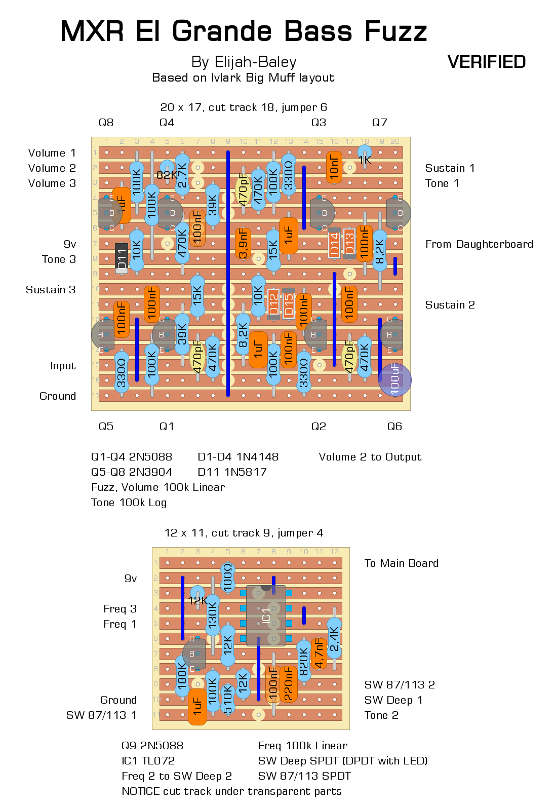
I have a new updated and corrected layout. Sorry, there's some minor mistake and some important mistake. I didn't replace the old layout to help you or other guys to read both here. I change the name of the Freq switch calling with its real name: Deep. Still not change the Freq pot name, I think we can call it Bass, or Deep, too. The important corrections are in the two upper corner. In the right corner: emitters of the two transistors, the third stage, was separated, and the 1k resistor to te Sustain pot was connected in a wrong way. Be careful the position of the parts and the cut track, the new the and the old we could need cancelled. This movements are because I added a 100nF in parallel with the 1uF, too. I did the same, just some moving, for the 1uF in the second stage, I added the 100nF cap. If you can or want to add it in other way it's ok, that part is alright. In the left corner you should move the 1uF one stripe down, from C to Volume 3. I guess that was the caused of the drop volume. Then there was the 1uF close the right side, it's just a 100nF cap. I corrected some a pair of resistors value. The 12k next the lower diodes is 10k, and the 12k resistor placed a bit higher is 15k. Those will not comprimise the working of the effect, but change both if you want the exact schematic. In the daughter board the 1uF output cap was a mistake. The right cap was simply the 100nF on the main board, already. You can just move the output of the daughter board after the 100R resistor. it's been a bit of a messed up job, but I hope we're nearing the end, now!  Update: VERIFIED 
I build pedals
|
|
Awesome, most appreciated. This has not been an easy one I am sure. I will work on making the changes this evening. Doesn’t look to hard. Thank you for all the time you have put into this one.
|
|
Ok, so I have made all the corrections and changes. The volume is up and there is plenty of it to spare. The fuzz is working great. The tone pot works great. The freq pot works great in both directions. I set it at noon and adjust either way from there . Seems to work great that way. The deep switch works great. The only thing that seems a little odd and it just may be the way it’s supposed to be, the 87/113 switch. You don’t really hear it doing anything unless the freq pot is all the way up or all the way down. In between that you don’t really notice it doing anything. Overall this is very useable and sounds great to me. I can deal with the 87/113 switch the way it is. The freq pot really makes a difference when dialing your tone in.
Many many thanks FX- Fidden. Matt |
«
Return to Requests
|
1 view|%1 views
| Free forum by Nabble | Edit this page |

