MXR GT-OD: Mission Impossible

classic Classic list List threaded Threaded
19 messages Options
Reply | Threaded
Open this post in threaded view
|

MXR GT-OD: Mission Impossible

Kost1978
Hi guys,
the MXR GT-OD was my first pedal of choice when I started back in 2013. Not a smart move beeing a complete newbie and indeed the pedal did not work...

Fast forward in 2015, after 30 pedals or so succesfully built, I wanted to give it a try again and build a new GT-OD from scratch. Obviusly I was soooo confident of my building skills  that I even boxed straight away, without even test it first
What do you think?
No sound at all from the circuit...

I did not probe the pedal yet (too angry to even look at the thing right now...), just want to ask you guys if this IC readings looks fine to some of you:
(IC used=)5532
7,84 1---8 8,89
7,79 2---7 7,83
7,60 3---6 7,83
8,05 4---5 7,84

Thanks in advance.
Reply | Threaded
Open this post in threaded view
|

Re: MXR GT-OD: Mission Impossible

Ciaran Haslett
The most glaring problem is pin 4.  Its connected to ground so should read 0V
Reply | Threaded
Open this post in threaded view
|

Re: MXR GT-OD: Mission Impossible

Kost1978
Ciaran Haslett wrote
...Its connected to ground so should read 0V
And this means something really bad happened in my "building skills" cited before!

Thanks for the tip, I'll check what's wrong over there.

EDIT: is it possible it happened something wrong to the chip with wrong voltages arriving to it?
Reply | Threaded
Open this post in threaded view
|

Re: MXR GT-OD: Mission Impossible

induction
Based on the voltages, the most likely problem is a missing ground connection. Remelt your solder joints and measure again. If that doesn't fix it, post pictures.

Maybe somebody with magic powers can move this to the Debugging section.
Reply | Threaded
Open this post in threaded view
|

Re: MXR GT-OD: Mission Impossible

Ciaran Haslett
In reply to this post by Kost1978
That always a possibility I'm afraid.  I've gotten away with it before...and haven't other times.  Hopefully you've used sockets

I tend to measure the supply and ground rails at the socket...before putting the chip in.  Its mostly pointless measuring the other pins without a chip in as the voltages will most likely change under load.  It doesn't hurt doing it though and could potentially save a chip if you found a obviously high voltage reading.
Reply | Threaded
Open this post in threaded view
|

Re: MXR GT-OD: Mission Impossible

Kost1978
Well,
here I am, again!
I desoldered the socket, cleaned all the traces around the spot, resoldered the connections around there, cleaned all the spaces between all the strips (again, cause I ALWAYS do that after soldering the last cable of a new board), checked again the layout even with a "reverse" one to verify the board's back...
But I still get the same reading at the 4th pin and no sound (I did not sobstitute the IC causa I get the same reading even without the chip inserted).

I'm attaching some pics, maybe someone less tired (of this layout) than me could give them a look...


Thanks!
Reply | Threaded
Open this post in threaded view
|

Re: MXR GT-OD: Mission Impossible

Ciaran Haslett
Nightmare!

Pin numbering as follows

1-8
2-7
3-6
4-5

Few things you can check.

1. Check continuity between Pin 4 (bottom left) and the bottom row (ground)
2. Check continuity of Pin 4 to pin 8 (hopefully none)
3. Check the wiring of your power supply
4. Check continuity of ALL ground points on layout
5. Check that 100uF cap above the socket and confirm it is not shorted.
Reply | Threaded
Open this post in threaded view
|

Re: MXR GT-OD: Mission Impossible

induction
In reply to this post by Kost1978
I don't see any obvious build problems (so far).

Questions:
1. What is the other end of the black ground wire (bottom left hole of the layout) attached to?
2. What is the voltage measured on the ground row itself (bottom strip of copper)?
3. What are you connecting your ground lead to when you make these measurements?
Reply | Threaded
Open this post in threaded view
|

Re: MXR GT-OD: Mission Impossible

Kost1978
Ciaran Haslett wrote
Nightmare!
Trou word, man!

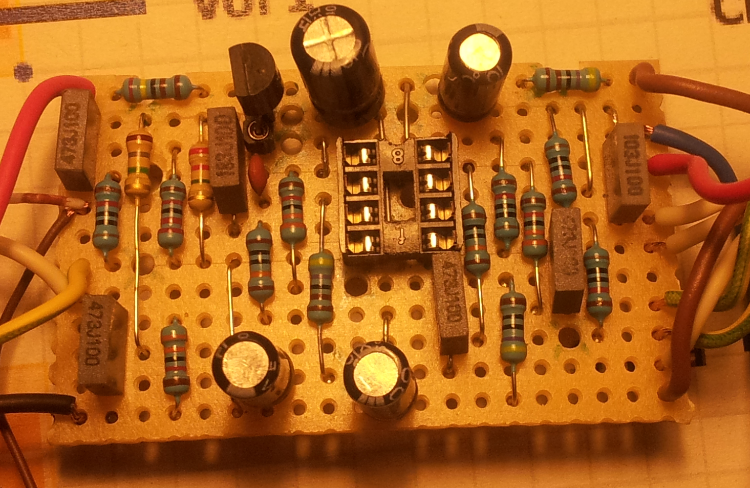
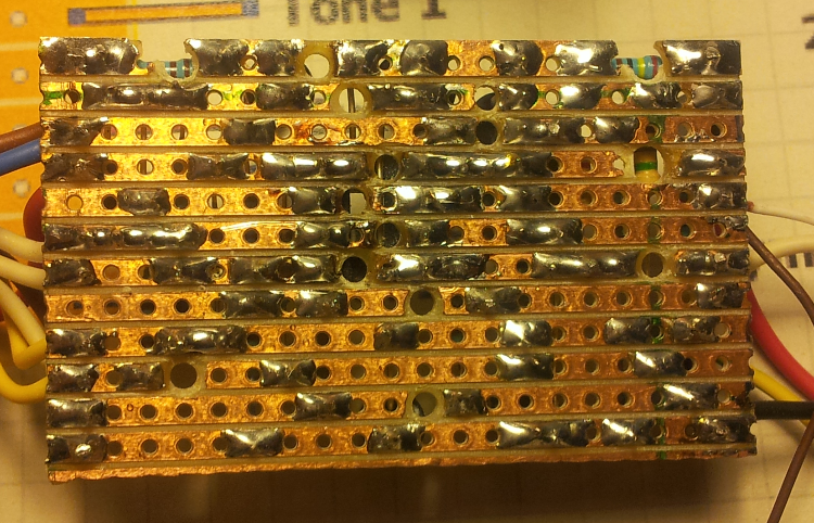
1. I remeber I checked the "zero reading" (which I don't have, of course) following the ground connection from pin 4 to the bottom ground strip: I got the same value (8,05) at the first step, given by the link which carries the ground connection to the bottom row, when I move more to the "ground exit" (black cable) I'm starting to get a correct "zero reading"...
[I hope this is clear enough for you guys, in my head it is, but revieweing my post I admit it's a bit difficult to read!]
2.3.4. I'll check and come back.


induction wrote
Questions:...
1. to the ground connection of my test box now, which work fine with other boards (at first the GTOD was wired and boxed, after the problem I got it out).
2. I'll check and report back, but as I said before coming straight from PIN 4 gives me a reading of 8.05, in other places I get 0.
3. to the ground connection of my test box.

I'll see what I'll get after some more testing with your tips, thanks again for your time and patience as usual.
Reply | Threaded
Open this post in threaded view
|

Re: MXR GT-OD: Mission Impossible

induction
The jumper from the ground row to pin 4 (rows 1 and 6 from the bottom) is probably bad. Looking at the back of your board, I suspect a cold solder joint on the side of the jumper that touches pin 4. Remelt that joint and see what happens.

It's hard to be certain from the picture, but I see a few more suspicious solder joints that I'd suggest remelting, including the ground wire on the bottom row. Might just be the picture, though.
Reply | Threaded
Open this post in threaded view
|

Re: MXR GT-OD: Mission Impossible

Kost1978
Hi guys, I'm probing the pedal right now, what a mess! http://3.bp.blogspot.com/-Is_QRKmH_gw/Uz5v-Ha7AjI/AAAAAAAAGgg/sdVsGMESxTk/s1600/MXR+GT-OD.png Quick question: do I need to get the "zero reading" all over the bottom ground row? The probed signal stops after the 1.8M res (row 10 from top), I changed that with no success. So I lifted the 4u7 CAP, no sound. Then I lifted the 100k res at row 4 and got some sound. Soldered back the 4u7 and again no sound. I finally lifted the 6-to-12 jumper, still no sound. So, I suspect something is wrong at the ground row, also because I get a high "hiss" all over the row beside at the exit ground cable... Anyway, I'm stopping now before getting more mad, maybe some of you got some ideas from my description... Thanks!
Reply | Threaded
Open this post in threaded view
|

Re: MXR GT-OD: Mission Impossible

IvIark
Administrator
That's part of a bias network for Q1, not in the signal path.  Check these components in order and let us know where the signal is dropping out:

Input
10K
47n
Q1 base
Q1 emitter
18n
IC pin 3
IC pin 1
10K
IC pin 5
IC pin 7
3u3
4K7
Volume 3
Volume 2
Output
Reply | Threaded
Open this post in threaded view
|

Re: MXR GT-OD: Mission Impossible

induction
In reply to this post by Kost1978
Kost1978 wrote
Hi guys,
I'm probing the pedal right now, what a mess!

http://3.bp.blogspot.com/-Is_QRKmH_gw/Uz5v-Ha7AjI/AAAAAAAAGgg/sdVsGMESxTk/s1600/MXR+GT-OD.png

Quick question: do I need to get the "zero reading" all over the bottom ground row?
Yes. Is that not happening? What measurement do you get on that row?

The probed signal stops after the 1.8M res (row 10 from top), I changed that with no success.
That node is AC ground. You should not have signal there.

So I lifted the 4u7 CAP, no sound.
Then I lifted the 100k res at row 4 and got some sound.
Soldered back the 4u7 and again no sound.
I finally lifted the 6-to-12 jumper, still no sound.
I can't tell if you're talking about no sound in the audio probe or no sound from the output. Can you clarify?

So, I suspect something is wrong at the ground row, also because I get a high "hiss" all over the row beside at the exit ground cable...
I suspect so, too.  Have you tried remelting the solder joints on the jumper I mentioned in my previous post?

Anyway, I'm stopping now before getting more mad, maybe some of you got some ideas from my description... Thanks!
If you are trying to debug or even audio probe this thing with just a layout and no schematic, you will drive yourself crazy. Most of the tests you describe above seem pretty random and are not likely to tell you anything useful. Try to follow the signal flow on the schematic when you use your audio probe. See how there are three main horizontal paths in the schematic? The top one is V+ and the bottom one is ground, both should give you nothing in the audio probe. The horizontal path in the middle is the signal path. Start your probe at the input and work your way toward the output, following the signal path. But first check that jumper I mentioned, and measure the voltage on the ground row at several places. If it isn't zero everywhere on that row, find out exactly where it changes and what it changes to.
Reply | Threaded
Open this post in threaded view
|

Re: MXR GT-OD: Mission Impossible

Kost1978
IvIark wrote
Check these components in order...
Hey Mark, thanks for the list, I'll for sure check them. I'll see now (after your tip and Induction's ones) I really need to follow a schematic to probe my board...

induction wrote
Is that not happening?
induction wrote
...check that jumper I mentioned...
It's not happening at all, I get "0" only at the exit cable, all around that row I read something around 8. Having disconnected the 7-to-12 link from row 7 (counting from top), I can say the problem is not coming from that particular row...

induction wrote
That node is AC ground
OK.

induction wrote
Can you clarify?
I mean I don't get the guitar sound at all. I was following a path (which now I know it's wrong...) whith the probe while strumming the guitar, some spots give me sound, but other don't. But we don't have to worry about that right now, "apparently" I wasn't following the correct signal path.

induction wrote
Most of the tests you describe above seem pretty random...
Well, I guess it's true, now I know. I'll try to follow your instruction and Mark's ones and see what I can get, for sure now I know a little better what to do thanks to all of you!


So, thanks a lot!
I'm sure this "mess" I'm into right now is helping me to learn something more about this great and big world!
I'll let you know how it goes...


Reply | Threaded
Open this post in threaded view
|

Re: MXR GT-OD: Mission Impossible

induction
Kost1978 wrote
It's not happening at all, I get "0" only at the exit cable, all around that row I read something around 8.
That clarifies a lot. If the cable itself reads 0V, but all of the copper on the ground row reads something else, then your ground wire has a bad solder joint. Remelt that joint and I bet your problem is solved (assuming you put all the other components and jumpers back in place first, of course).

induction wrote
Most of the tests you describe above seem pretty random...
Kost1978 wrote
Well, I guess it's true, now I know. I'll try to follow your instruction and Mark's ones and see what I can get, for sure now I know a little better what to do thanks to all of you!
No judgement implied. We all start out knowing very little, and we work our way up. One of the best ways to learn this is stuff is by debugging circuits that aren't working. That's also an excellent way to start learning how to read schematics, which is why I suggested it. You can build most circuits from layouts, but for debugging, you need a schematic.

So, thanks a lot!
I'm sure this "mess" I'm into right now is helping me to learn something more about this great and big world!
Exactly.

I'll let you know how it goes...
Please do. Us armchair debuggers learn from this just like you do. It's very satisfying for us to find out what solved the problem and what didn't.
Reply | Threaded
Open this post in threaded view
|

Re: MXR GT-OD: Mission Impossible

Kost1978
Well,
after some "useless" debugging I decided to give up, this is another board that's going into the "recycle bin"...
Just to let you know, the sound was already stopping at Q1 emitter and I couldn't figure out why.

The funny thing is after this "failure" I started a double pedal on the same board (something I've never tried before, a 19x38 board!) with the Cornish SS-2+G2, I completed it just yesterday and you know what? Working like a charme at the first test!

The "debugging session" was quite helpful anyway, I learned how to better follow a schematic after your tips, so thanks to all of your kind suggestions!

Anyway, I guess the MXR GT-OD will have in the not-so-near future another chance, right now I'll try not to think about it!
Reply | Threaded
Open this post in threaded view
|

Re: MXR GT-OD: Mission Impossible

Beaker
It happens to all of us sooner or later. Build a board, test it, and nothing...

I built a Rams Head Big Muff about six months ago, and got no sound out of it. Checked for everything - cuts and links, component placement, component orientation, component value, soldering errors, off board wiring - everything checked out fine, but no sound.

Built it again, and it worked perfectly first time.

I think it's a demonstration of Murphy's Law of Pedal Building in action.
Reply | Threaded
Open this post in threaded view
|

Re: MXR GT-OD: Mission Impossible

rocket88
Administrator
Yep. We all have the one pedal we can't get working. Mine coincidentally is also of muff liniage, the catalinbread loaghtan. I built it twice from two different verified layouts and nothing. I swear I'll try again and get it working, but it still kills me that I couldn't get anything out of it, especially after building all the muffs and muff varients without even a hick up.
Reply | Threaded
Open this post in threaded view
|

Re: MXR GT-OD: Mission Impossible

Kost1978
Well, at least I'm not the only one who's getting the same disastrous result with one effect and TWICE!

Building the MXR GT-OD back in 2013 was an easy way for me to compare a clone with the real thing, cause the other guitarist if my band is playing one: it's really funny I still couldn't do that after many builds!
You know, just to show to the "skeptical guitarists" out there sometime a clone can sound very close to the original thing...if not better!

Anyway, maybe I'll get luckier next time!