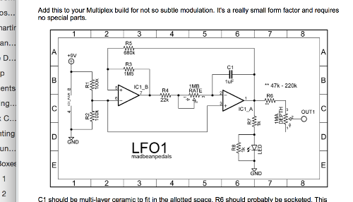
Mad Bean Modulaterator
|
This looks like a nice circuit to add to PT2399 delays, such as the Mad Prof Deep Blue.
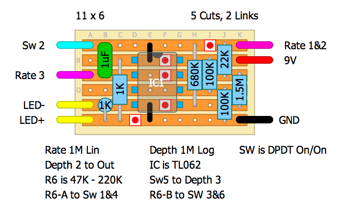
Ive worked out a veroboard but I think it is a little large (13x10) - can any one take up the challenge to make it smaller?  IC should be either TL072 or TL062. I was also going to socket R6 and when I found two values I liked (probably the two extremes) I was going to add a SPDT to switch between my two choices incidentally, if you're wondering how this fits in to the deep blue delay - it would tie in to pin 6 of the PT2399; before or after the resistor on pin 6 (this resistor sets the minimum delay time on the deep blue style delays) - all faithfully copied from mad bean pdf http://www.madbeanpedals.com/projects/index.html Hope you can help :) |
|
This post was updated on .
If you use a DPDT (and 1 standing resistor) you can get it smaller...
 Just use a breadboard to find your desired values for R6 before you solder them to the switch. Good luck. |
|
Should it not be: SW5 to Depth 3, instead of SW4?
|
|
Typo. Cheers Neil. Sorted
|
|
Excellent love it - much neater than mine, the links above and below the chip really neaten things up.
Just to clarify (my idiocy) - is pin 1 on the depth pot left unconnected? Thanks so much for your help - I will build it and get back once verified UT If this works it is a great/simple mod board that would give an alternative to the LDR/LED version - could we add it to the layouts section once verified? |
|
You can link lug 1 to lug 2 if you want, or leave it unconnected. It's a simple variable resistor (rheostat) configuration. If you verify it, I'll clean it up with all the proper labelling/notes etc and add it to the contributions section.
Good luck. |
|
will do.
|
|
Built this today - consider it verified.
It is a great addition to PT2399 delays and adds a nice warble. In common with many Deep Blue style delays it is the time resistor to pin 6 which needs this signal adding to. You can add it before or after the resistor with slightly different results - my preference is between the resistor and pin 6 As far as the choice of R6 resistors go 220k gives a nice variety of effects from subtle to extreme depending on the delay time. using 47k for R6 was more extreme from very wobbly to self oscillating weirdness, which it achieves too easily. Ive not tried any other values yet, but I think I will increase 47k until the osc happens at extreme settings rather than most. Interestingly the depth control, and to an extent the rate control have quite a few areas of 'nah!' in their sweeps - Im wondering if changing the value or putting an additional resistor in series or parallel with the pot will improve their usability I will feedback with my chosen values later, but for now this one is good to go :) Thanks for your help :) |
|
Nice one! I'll sort it out in a bit. Glad you're getting use out of it. Have you an oscope? You could hook it up to one and view its output...then modify values etc and see what difference they make.
|
|
the 2 pots and the resistor work depth, rate and pitch modulation, but that is as a ratio to the delay time.
I modded my deep blue to have double delay (simple, effective but dirty mod - just extra switched resistor in series with the delay pot doubling its resistance range) SO the delays go from slap back to about 700ms. the suggested resistors for the pitch mod switch didnt work for me over these ranges as the pitch mod produced was too extreme. Pitch result: 47k - extreme modulation with areas of oscillation, very creative but not for me this time 200k - less extreme but still quite radical 360k - about the most pitch mod I wanted for this particular flavour; I chose this as my 'radical value' 1M - softer drifting towards tape, was my favourite generally, but I wanted more of a difference from 360 1M8 - very tape like drift available (depending on depth set) useful for the longer delay settings 2M2 - at its least depth and rate almost too subtle for a delay, but at higher mix levels was very nice In the end for my needs I chose 360k and 1M8, and they come highly recommended :) if I get a chance I will build the LDR modulation daughter board and compare the two, but as a cheap daughter board to mod an analogue delay this is great. thanks again Shaun |
|
Is the 1.5M necessary or I could swap for a 1M? I'm asking because with 1M in place of 1.5M seems not to work at all. I've built it and there's no lfo, the led stays always on and the depth just reduces the voltage output (from 6 to 2 volt more or less).
|
|
The youngest busted my macbook so I haven't got round to tidying this up for Contributions yet Shaun. Once its repaired I'll add that great info you posted. Cheers for that.
edo....The 1M5 is partially responsible for how fast the LFO cycles so it's not critical. Sounds more like a build/part error to me. Maybe try reflowing all the joints again or try changing the IC? Also, there's no cut between pins 3 and 6, which is a bit different to most layouts. Did you use the switch? My notes weren't very clear on that sorry (although if your voltage is changing then it sounds like you got it). If still no joy post some hi res pics. Good luck |
|
Refollowed all the circuit. To me seems alright, but here's a pair of pics.
image582.jpeg image858.jpeg Here are the voltages: 1 4,5 2 4,5 3 4,5 4 0 5 2,1 6 0 7 0 8 9 I think something is wrong. The switch it's wired correctly and the white wires are 9 volt and ground. I've used 500k instead of 1M pot. |
|
Well, I found a micro solder bridge, got rid of it and the lfo was working only at maximum rate. When I put the rate at minimum I have no lfo. While checking for the problem. I accidentally touched the raw that connects pin 3 to 6 and it started to works again. Long story short: I put 1M resistor between that raw and ground. Now I'm wondering why I've needed to do that..
|
|
Sorry man...was at a RHCP gig last night. Jesus they need John back
 Well pin 3 and 6 are connected to each other so they should have the same voltage. They are also connected to the vbias network 9V > 100k > 100k > GND, where the junction is 4.5V. So your pin 3 had 4.5v but 6 was 0? It must be a cold joint or a dead IC. Putting a 1M between that row and ground fixed it? That almost sounds like the bottom 10K in vbias wasn't connected properly and the new 1M took its place. 9V > 100K > 1M > GND. Again sounds like a cold joint. So I can only suggest reflowing your joints. Clean between every strip, especially the IC pins Personally i'd just build it again and socket the IC. You're already way more hours into debugging than it takes to make another. |
|
Man, John was far better. I can't really enjoy the new formation. By the way, now the 3/6 raw has a 4.5 volt, but it need to be connected to ground to get the slow rate. The main reason I won't build another one is that I'm out of strip boards, so I have to make it working.
|
|
In reply to this post by Ubertech_s
Ive used this for a while now with a deep blue delay and it is fine
however, Ive now boxed the DBD with a Boogaloo trem which work really well, but ive realised that the sine LFO for the delay mod can be quite obvious in some trem settings is there some way of changing the LFO to a ramp/square/pulse? thanks Shaun |
|
Hello,
Thank you for the layout! I plan to make this daughter board to add an LFO to an MS20 filter. Which kind of 1µF capacitor should i use : a big film/box, or a smaller ceramic, or tantalum ? Does it matter much ? |
|
I just built it, and it is a very nice little circuit :)
- It works very well with PT2399 delays and chorus (modulating pin6); - It doesn't work with the MS20 filter i attempted to modulate : i guess the signal delivered is not the expected voltage for the MS20 filter. It's a great daugtherboard to have for other circuits. |
|
How does this connect to the delay board ?
|
«
Return to Mod Boards
|
1 view|%1 views
| Free forum by Nabble | Edit this page |

