Madbean 4:1 Compressor [Semi-Verified]


|
This post was updated on .
UPDATE [20210605]: minor layout change to create more space for electrolytics. Functionally the same as before.
UPDATE [20210616]: The layout below has been changed after building and experimenting in order to make more room for the vactrol. If you're building this then, (a) make sure you have the latest version, and (b) make sure you insulate the vactrol from the jumpers underneath it. If you're using the default (VTL5C3), the plastic body of the vactrol will do this just fine; if you roll your own opto-coupler, make sure to use enough electrical tape / shrink-wrap / air-gap to do the job. See discussion below for more. Hey all. I got interested in trying the Madbean 4:1 compressor after jamming with a friend's Afterlife, but unfortunately Madbean isn't shipping PCBs to the UK at the moment, and nobody appears to have done a decent vero layout that I can find, so I thought I'd chance my arm using the schematic and build documents that are available at Madbean's site. The circuit is essentially the Flatline/Afterlife compressor with a mostly separate 'parallel' clean blend. Misleadingly, 'Sustain' is the actual 'amount' of compression (strictly, it's the signal gain through a fixed threshold), whereas 'Compress' is the *level* of the compressed output, and 'Clean' is the *level* of the clean input signal; both of which are buffered through opamps and, I'm told, can go somewhat above unity. You can set the blend/mix level by trading one level control knob off against the other. If you're looking for a 'character' compressor, this might not be it; the word 'transparent' tends to get used about the Flatline / Afterlife variants, and they're pretty highly regarded. 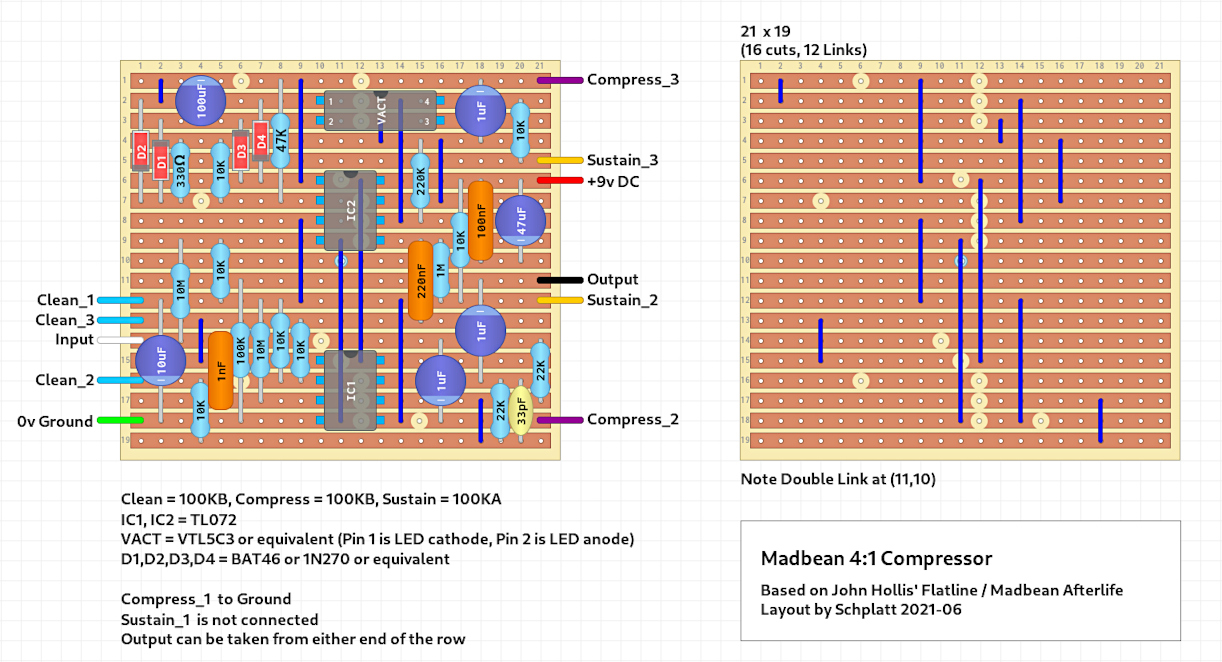 If you have a go at this, I thoroughly recommend going to get the build docs from Madbean's website as the PDFs contain both BOMs and shopping lists as well as the schematic, which simplifies the prep a lot. Note: The overload-protection diode and current-limiting-resistor for the LED are both included / counted in the Madbean documents but are not included here. In particular, in the build documentation for both the 4:1 and the Afterlife, Madbean goes out of the way to stress the importance of the Vactrol. The circuit apparently works best with an original VTL5C3 or the genuine substitute made by Xvive and sold by Smallbear in the US and Thonk in the UK. Many of the third-party sellers on ebay are not selling the real version of either and people have had problems because of it. It's possible that they discourage people from rolling their own just because of the multiple combinations and mismatches that can happen and they're tired of dealing with them. If I was going to try rolling my own, I'd probably go with a GL5539 LDR and an orange or yellow LED, partly as that seems like a semi-decent match for the resistance-characteristics and partly because people have had success with that combination when building other compressors which also use the same vactrol in similar circumstances. I'm categorically not promising or guaranteeing anything; I've not tried it -- it's just where I would start. I have a VTL5C3 in the mail from Thonk, so I'll probably just use that. [Out-of-date]: If your vactrol (of whatever flavour) is larger than the space in the layout, you can use the holes to the right of the vactrol, on the other side of the jumper, for pins 3 and 4, for more space. You can also move the 1uF cap to the right to create even more room in extreme cases. [Note: This paragraph is the original text of this post, however the layout above has already been changed to reflect this]. Talking of caps, you might need to be careful when buying / choosing your electrolytics. There is room for all of them if chosen sensibly but, in particular, the 100uF cap in the top left corner could be a problem if you pick an unexpectedly large one as it's only a three-hole straddle. There's nothing else standing-up in that part of the board, though; so you might be OK regardless. A quick note on the diodes: Madbean used 1N270 germaniums in the Afterlife, but _some_ 1N270's can be quite long or wide (almost resistor-sized), so they switched the diodes to BAT46 Schottkys for the 4:1 PCB to save space. Either should be fine here, as there's more room on the vero than on the PCB, plus there's room in the layout area where the diodes are located to reshape the leads if need be. D3 _might_ be tight if you've got a particularly long 1N270, but nothing that creative (and _careful_) lead-bending can't deal with. Stick with the BAT46 diodes if you want to be sure. Because of the way the parallel processing is set up, and the fact that the original PCB is dual-layer with some clever Via connections, it's tricky to make a layout for this that's both compact and doesn't do anything too OCD-triggering. You can make a layout more compact than this if you make a wider board (say 25 columns) but then it won't fit in a 1590B, and you can go even more compact if you start doing 'triggery' stuff (like diagonal / horizontal components; standing axial components, overlapping / outboard jumpers etc.), but this is about as tight as I could get it while sticking to the 'IvIark principles'. It's good enough for my purposes. There's still some (literally) borderline stuff, like components on the board edge where there are no connection leads, but I can live with those. I won't get a chance to build this for a few weeks, so I thought I'd put it up in case anyone fancied a look at it in the meantime. |
|
|
This post was updated on .
UPDATE
I finally got a chance to put some work in on this. Veroboard cut and marked: 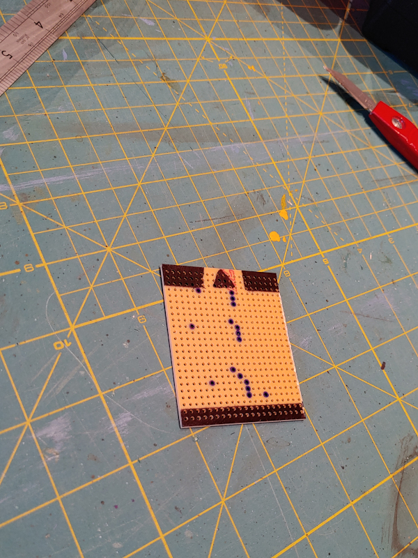 Cuts made:  Links / jumpers inserted: 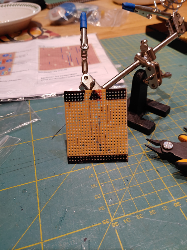 Board mostly populated: 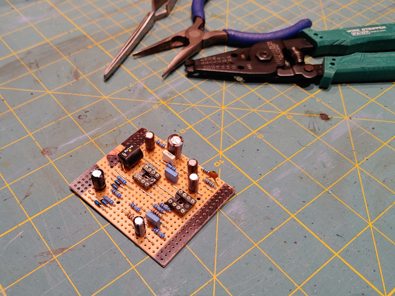 A couple of notes ... If you're using polybox caps for the medium-value caps (orange in the diagram), be aware that you might have to engage in some partially-skilled play with needle-nose pliers and reverse-action tweezers to get them to fit. The biggest span here is five rows (jumping over three stripboard rows), and this is doable with a standard polybox, but it is pretty much the limit of its range in terms of shortest leg size. If you get polyboxes with longer legs then it's not a problem. If you're not comfortable with different leg bending techniques, or you don't have something like reverse-action tweezers to peg the caps in position while you solder them, I'd be tempted to get non-boxed polyester film or mylar caps and not have to worry about it (they generally have longer legs by default). I was having some trouble with my SIL sockets / pin headers which I was intending to use for the vactrol. Firstly -- and I don't know if it was just this particular batch -- they seemed to break fairly easily. I've never broken socket pins before, but one broke simply from a very minor position tweak. Secondly, after I desoldered and replaced the broken socket, they didn't seem to provide much grip on the vactrol legs. The legs were too slippy in the socket for my liking. So I decided to bite the bullet and hard-solder the vactrol straight into the board (using heat-sinks while soldering). There are a couple of things to note about this. [Out-of-date]: Firstly, if you're using a VTL5C3, as mentioned in the initial post, you're going to have an easier time going into the two spaces to the right of the jumper-link at (16,2) and (16,3). That is: move pins 3 and 4 of the vactrol two spaces to the right. You can go into the original spots if you want, but it's a tight bend. I will probably update the layout to reflect this if the circuit actually turns out to work when I test it. [Note: This paragraph is the original text of this post, however the layout above has already been changed to reflect this] Secondly, if you choose not to use sockets as I didn't, you need to make sure to dog-leg the vactrol legs so they don't risk connecting to the jumper, as in the following picture. (Pin 4 touching the jumper is fine, as they're common anyway, but pin 3 must not touch): 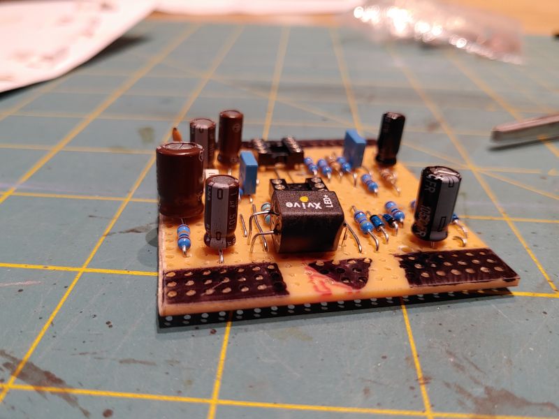 Lastly: all tucked-up and ready to go. I've used longer runs of stranded wire for the connections on this, as I'm not yet quite sure what enclosure / application it's going into if it works: 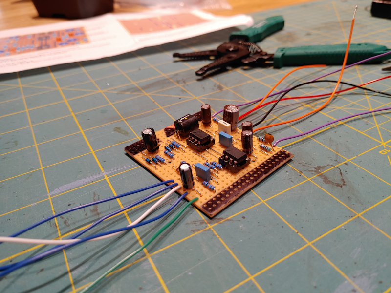 I'll hopefully get a chance to test this in the next week. Will add an update when I do. |
|
|
In reply to this post by Schplatt
OK. Managed to snag some time this evening to test it.
It works. Or very much seems to. Thanks to the op-amp buffers, both the compressor side and the clean blend side of the signal path have more than enough gain to go well above unity. If you turn the 'Compress' knob completely down (thus muting the Flatline / Afterlife portion of the circuit), you can essentially use the 'Clean' side of the blend as a gain control of sorts, thus turning it into a sort-of boost pedal / clean preamp. It sounds absolutely superb. It's very transparent at low 'Sustain' settings -- almost in an "Is this thing on?" sort of way, but by about half-way on the Sustain knob the compression becomes noticeable, and it's pleasant -- very smooth; almost -- I hate to say it ... -- "creamy". At high settings, it never develops the extreme rubber squish / quack of the Ross/Keeley/Dynacomp (it's too smooth for that) but the 'effect' is strong and very clearly present; about 60% of the way to "extreme country" territory. I don't really understand the people who've said they can't hear it; it's very obvious. It's even more obvious under the fingers. One of the things I was pleasantly surprised by was the gradualness with which you can 'feel' the change in the compression as the 'Sustain' goes up. The pot is logarithmic, but maybe the human touch sense is as well, because you can 'feel' the decrease in finger dynamics kick in fairly linearly as the pot position goes clockwise. The biggest smile came on bass. This thing is amazing on a J-bass with Labella flatwound strings. I only meant to test it diagnostically -- i.e. check and make sure everything worked as expected -- but I ended up just playing the bass for nearly an hour and experimenting with the blend variations. This was particularly satisfying as one of the reasons I wanted to try this was that I'd heard the Flatline / Afterlife / 4:1 were good on bass and my Keeley-variant isn't (loses sub). I only managed to play the Afterlife with guitar at my friend's place, so I didn't know for sure. Now I do. The only slight downside was that I was picking up a very small bit of noise / whine in the circuit at very high sustain settings. This is partly a problem of compressors anyway -- they magnify the low-intensity noise up into the 'very noticeable' range -- but it could be another thing. I was testing this with no shielding as an open circuit with lots of cable length in a room with two electricity mains loops, a cheap power supply and CFL + LED room lighting just under my feet in the room below, so I'll report back once I get this into a shielded enclosure. It's not a game changer anyway; it only manifests itself at the most extreme end of the compression. There was nothing noticeable on the clean side. The good news is that, other than the minimal high-intensity-settings whine, there is no general noise floor to speak of -- no background hiss and no hum other than mains hum from the pickups when not hum-bucked. Now that this seems to work, I've changed the layout above to reflect the change in vactrol position. I've moved the jumper away from the vactrol legs (pins 3 and 4) too, as there's now more room under the vactrol. The circuit is unaltered otherwise. I'm going to label this as 'Semi-verified' until a third party makes it -- not sure if it's particularly kosher to validate your own layouts, but it does seem to work. And lastly, because the immutable law of the internet states that everything is improved by the presence of puppies, this was my testing set-up: 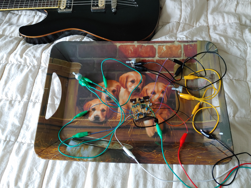 I'll report back once I get it into some type of shielded enclosure. |
|
|
In reply to this post by Schplatt
OK. Another month, another update.
I put this in one of my patented I-can't-be-arsed-to-order-a-Hammond oversized birch plywood enclosures. It still works absolutely fine, as far as I can tell. The high-pitched-whine-at-extreme-sustain-settings mentioned in the last post is gone -- I suspect it was the CFL / LED transformers beneath the floorboards acting on an unshielded circuit with a lot of wire -- but, whatever it was, it has gone now. At first I thought the circuit was playing up, as the Compress volume was going way above unity, the Clean volume was only having a slight effect, and the circuit wasn't getting muted with both volumes flatlined, but it turned out that I'd forgotten the connection from Compress_1 to ground (somehow missing my own instructions in my own layout diagram ...). Anyway, once that was taken care of, it behaved as before: pretty awesomely. I've played with it a few times since and it's still doing as expected. I'll try and work up some sort of audio demo next time I have a cab mic'ed-up (which could be a while, so don't hold any breath), but until then, it's pretty-much verified. Pics:  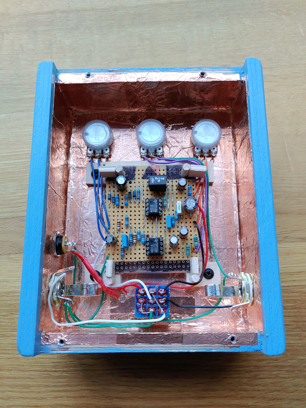
|
«
Return to Unverified Layouts
|
1 view|%1 views
| Free forum by Nabble | Edit this page |