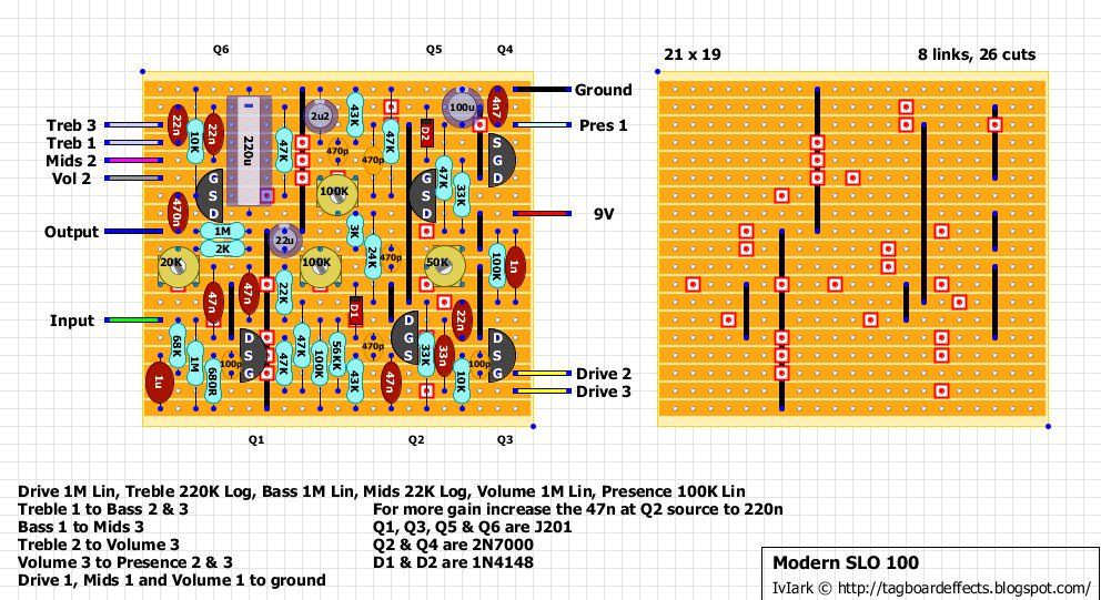
So i've been messing with this some more and discovered a few things.
looking at the linked schematic, there is a mistake in the power section.
The voltage divider at R21/R22 is wrong. with a 24k/33k divider you will not get 4.5V out with a 9V supply. it should be 24k/24k or 33k/33k. This will give an improper pull up voltage going into Q2 and Q4.
This is correct in the "original" shown above, but in this one:

the values are incorrect. the offenders in question are the 24k resistor above and to the left of Q2 and the 33k immediately to the right of q2.