Modified BeeBaa

classic Classic list List threaded Threaded
14 messages Options
Reply | Threaded
Open this post in threaded view
|

Modified BeeBaa

rocket88
Administrator
I was thinking about building a BeeBaa, but I want to do a stripped down version. So, I really don't need or want the boost, and the tone select switch. Could someone with more skill then me be able to put together a layout? BTW, I plan on playing with some of the values to get it a little darker and heavier too, but the original just is just way more then I'm looking for, but has the fuzz I'm after. Thanks guys.

Reply | Threaded
Open this post in threaded view
|

Re: Modified BeeBaa

Neil mcNasty
Try this one:


Here is one with the Tone Switch intact:


I have not verified them yet, but they seem ok as far as I can tell...
Reply | Threaded
Open this post in threaded view
|

Re: Modified BeeBaa

boratto
This thing has a silly name, but SOUNDS HUGE. I see in a old schematic that uses 2SC828. Any change to put these on this circuit?
Reply | Threaded
Open this post in threaded view
|

Re: Modified BeeBaa

rocket88
Administrator
This post was updated on .
thanks McNasty. just a question, win the first layout you did not put the tone switch, which is perfect, but which tone setting did you out on the board? how much do the two settings differ? Cause I was thinking about playing with input caps on a rotary switch to control the tone instead of the two different tone filter settings like the origin.

as far as i know the original used 2sc828, and the schematic i posted was made by generalguitargadgets, with 3 changes.

1 - transistors to use easier sourced ones that sound similar
2 - there is an added polarity protection cap (c10 i think)
3 - there was a cap added to smooth it out a bit (c18 i think)

so i would assume you should be able to use the 2sc828's if you got them, but made need to change the biasing resistors.
Reply | Threaded
Open this post in threaded view
|

Re: Modified BeeBaa

Neil mcNasty
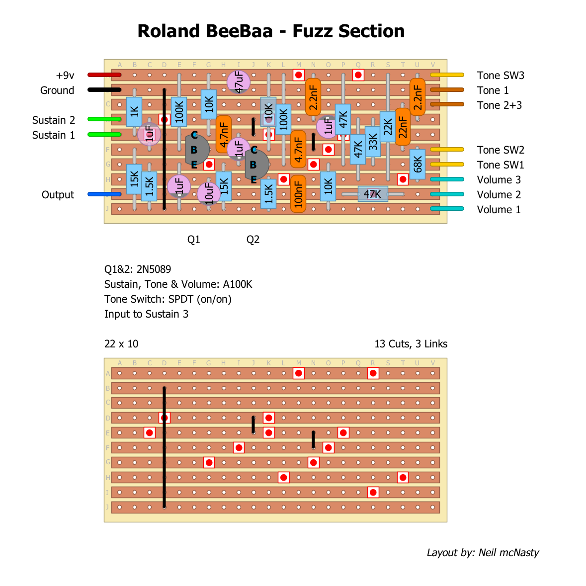
The Tone setting I removed was the scooped one (thinner sounding), meaning I removed: C14, C15, R20 & R21.
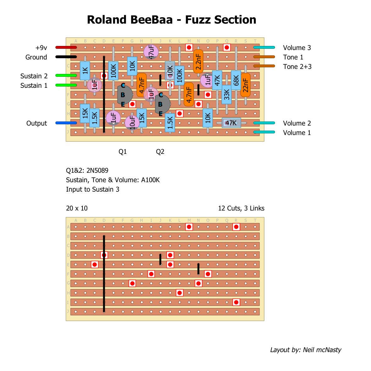
I would also suggest that you socket the 2.2nf cap and experiment with some higher values to see what happens. My logic tells me that this should give you a bit fatter sound.
Another thing you could try, is to build the one with the Tone Switch, but replacing the switch with a pot, creating a balance pot between the two Eq settings. That should give it a wider range and possibility.

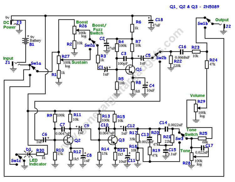
A small note on the Cap changes that you mention: C18 is added for power filtering (this can be of a higher value if want), not polarity protection. Diodes are used for polarity protection, and this schematic does not have any such thing, so i did not include one either.

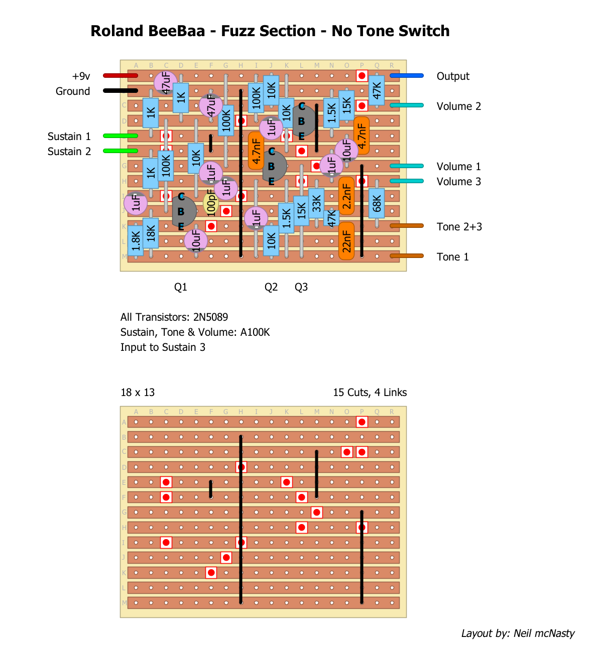
Boratto: note that the SC series transistors has a different pinout than the 2N series, so you might have to twist and bend some of the legs for it to match the layout.

On a side note:
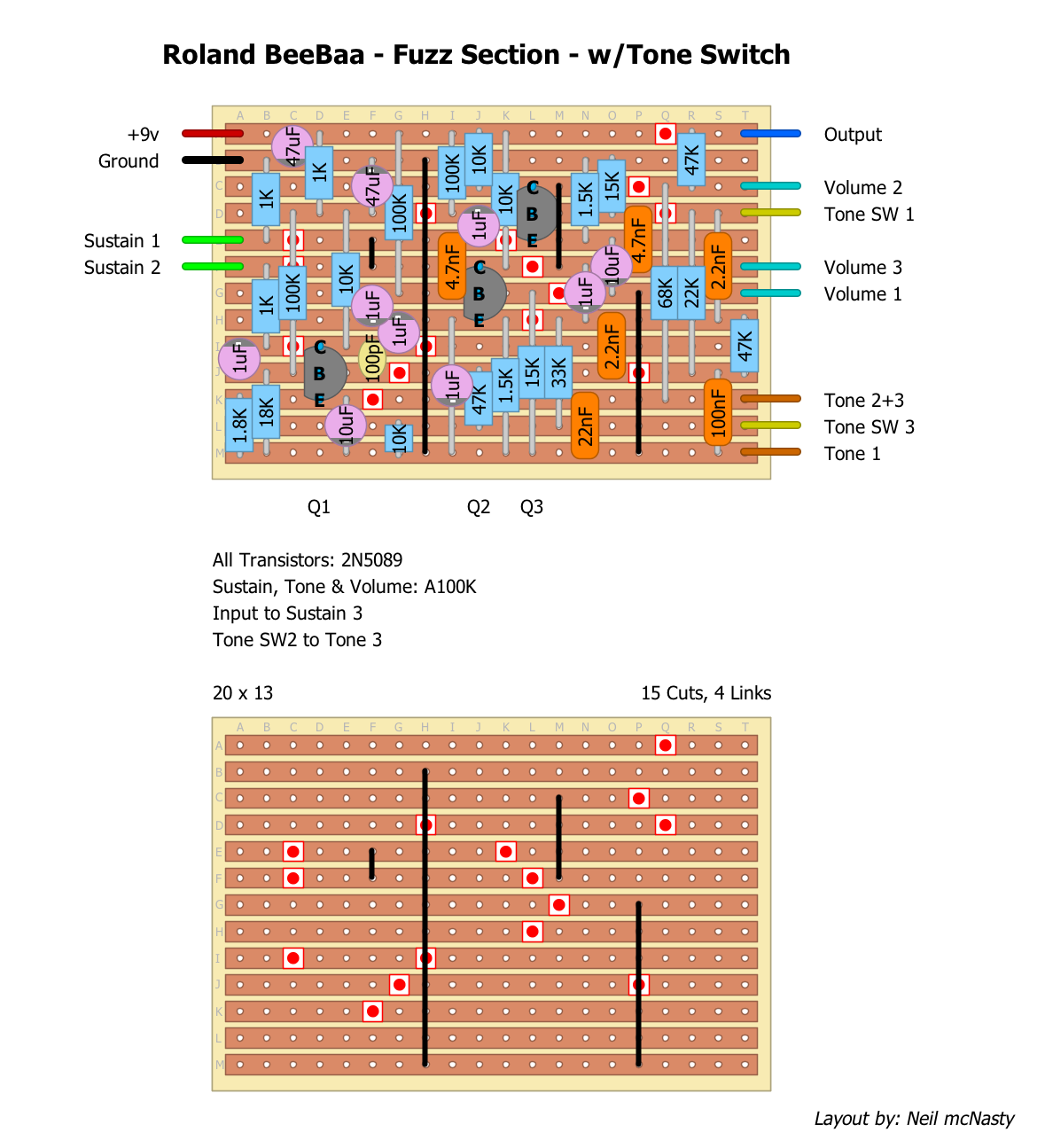
I noticed that there is a track cut that is not needed, below the 1uf cap to the right (on both layouts).
It does not affect anything, but I just wanted to mention it...

For those of you who enjoy this kind of monstrous sound should check out my heavily modified version of the Roland Double Beat: The "Huzzle & Cuzz Fuzz" that I posted a few days ago.
You can find it in the Contribution section at the end of the "Roland Double Beat Fuzz Section" thread.
It is insanely huge sounding, but might prevent the rest of your band from cutting through the mix
Reply | Threaded
Open this post in threaded view
|

Re: Modified BeeBaa

boratto
This post was updated on .
HA!
Im gonna after a Holy Huzzle & Cuzz Fuzz.. make them bleed! :)
Reply | Threaded
Open this post in threaded view
|

Re: Modified BeeBaa

rocket88
Administrator
In reply to this post by Neil mcNasty
man, sometimes i wonder what my hands are doing, i was thinking that it was for power filtering, but wrote polarity, I'm definitely going to play with this and see what else i can get out of it from some changes. btw, that Huzzle & Cuzz Fuzz looks insane. do you have a sound clip of it?
Reply | Threaded
Open this post in threaded view
|

Re: Modified BeeBaa

induction
In reply to this post by Neil mcNasty
This layout is missing a transistor. Looking at the schematic, the boost mode is one common emitter stage, but the fuzz mode has three common emitter stages. In other words, in fuzz mode, this circuit uses the boost stage as the input to the fuzz stage (the boost stage is in the circuit in both modes). This layout has only two transistors, so I assume you've only included the bottom half of the schematic. This is unlikely to sound like the original pedal without that extra input stage.

It might still sound good, but I wouldn't expect it to reproduce the sound of the original pedal.

Also, the tone section in this pedal comes at the end of the circuit. Input caps come in front of the circuit (obviously). There is a huge difference in tweaking the frequency response of the signal being fed to the fuzz and doing the same thing to the signal coming out of the fuzz. (That's not to say you shouldn't do it, but it's something to  be aware of.) For example, letting more bass into a fuzz tends to make it sound farty (distorted low frequencies in general sound this way) and less cutting. Letting more bass out of a fuzz will just retain more low end (assuming the original output cap is cutting some of the bass out, otherwise it won't change anything). If you want to tweak this circuit, I recommend breadboarding it before you build it. Especially if you decide to change the circuit topology.
Reply | Threaded
Open this post in threaded view
|

Re: Modified BeeBaa

rocket88
Administrator
Thanks induction. I was going to breadboard it too, but figured if there was a layout it would make the process a little quicker. I thought the switched added the boost stage and is essentially a treble booster. If the boost stage at the beginning is in the circuit no matter what then how does the boost switch work? Does the switch take the fuzz out of the circuit rather then taking the booster out of the circuit?

As far as moding this I was thinking about adding an input cap switch to alter tone of the fuzz, in addition to tweaking the filter at the end of the circuit.
Reply | Threaded
Open this post in threaded view
|

Re: Modified BeeBaa

Neil mcNasty
Of course! Thanks for noticing!
How silly of me to not notice something that obvious.
I'll get on the case and redo the layout tonight.
Will be back soon with the correct version....
Reply | Threaded
Open this post in threaded view
|

Re: Modified BeeBaa

induction
This post was updated on .
In reply to this post by rocket88
rocket88 wrote
If the boost stage at the beginning is in the circuit no matter what then how does the boost switch work? Does the switch take the fuzz out of the circuit rather then taking the booster out of the circuit?
That's exactly right. It's not fuzz plus boost, it's fuzz or boost. It takes advantage of the fact that the fuzz circuit is essentially just three cascaded boost circuits. Isolate one of those stages and you have a boost. Use all three and you have a fuzz. In boost mode, changing the sustain pot has no effect. In fuzz mode, changing the boost pot has no effect. This lets you set the fuzz control independently of the boost level.

If you don't like the boost mode, you can do away with the boost pot, the boost/fuzz switch, R2, R22, R23, C5, and C16, but you need to keep the rest of the boost section.

Actually C16, R22, and R23 are in the circuit in both modes, but in fuzz mode, they just act like a treble rolloff. You could try keeping them, to see how much difference they make, but I suspect it won't be much. If you plan to rework the tone section anyway, then you're probably better off without them. You can make up the difference by adjusting C13 and R19 if necessary.

If you don't want the boost mode and you want more volume from the fuzz section, you can probably reduce or eliminate R24 (replace it with a jumper). This will decrease the output impedance. Try it on the breadboard first. It may make it brighter, and/or change the interaction between the fuzz and whatever comes after it in your chain. (If you decide to keep the boost mode, you probably want to keep R24.)

As far as moding this I was thinking about adding an input cap switch to alter tone of the fuzz, in addition to tweaking the filter at the end of the circuit.
That's an excellent plan. Try it on the breadboard first to see what sounds best. This circuit will probably respond noticeably to transistor swaps because the effective resistance of the transistor determines the amount of gain in each of the stages. It might be worthwhile to swap out the transistors on the breadboard to see what you like best. You can mix and match, too. They don't all have to be the same type.
Reply | Threaded
Open this post in threaded view
|

Re: Modified BeeBaa

Neil mcNasty
OK! Forget about my layouts above.
This one is the one you'll want to try:


A version with the tone switch intact is coming soon as well...
Reply | Threaded
Open this post in threaded view
|

Re: Modified BeeBaa

Neil mcNasty
In reply to this post by rocket88
And the one with the Tone Switch Intact:
Reply | Threaded
Open this post in threaded view
|

Re: Modified BeeBaa

rocket88
Administrator
I forgot thank you McNasty. I'm going to build this as soon as I get a chance to build again and let you know how it goes, but it looks good to me according to the schematic.