Moosapotamus paralooper phase inverter

classic Classic list List threaded Threaded
11 messages Options
Reply | Threaded
Open this post in threaded view
|

Moosapotamus paralooper phase inverter

FabGTO01
Hi everybody,

I want to make a Moosapotamus paralooper and I would like to insert a phase inverter switch as in in the ROG Mixer/Blender. Could someone tell me if the switch in the schematic below could work or if I need to ad other component and wire.


Thanks,
Fab
Reply | Threaded
Open this post in threaded view
|

Re: Moosapotamus paralooper phase inverter

cylens
While I cannot answer your question (... sorry), I can point you to this:

http://freestompboxes.org/viewtopic.php?f=28&t=10347

I've been looking for ways to make a phase inverter and have settled on this. Used it many times, works great.
Reply | Threaded
Open this post in threaded view
|

Re: Moosapotamus paralooper phase inverter

Freppo
In reply to this post by FabGTO01
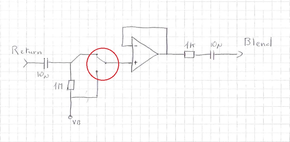
That won't work as an inverter, and the switch will only kill the signal. For a op amp buffer to be inverting, you need to use the inverted (-) input, with an input resistor and a feedback resistor of the same value.


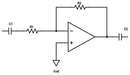
R1 and R2 can both be 10K.

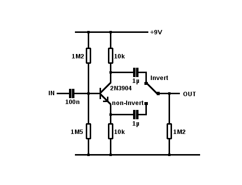
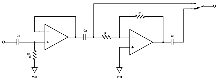
You could have a non-inverting buffer (as the one you posted) and a inverting buffer in series (from the same dual op amp), and simply have the switch select output from one or the other


I hope that helps
/ Fredrik
check out my building blog at www.parasitstudio.se
Reply | Threaded
Open this post in threaded view
|

Re: Moosapotamus paralooper phase inverter

Freppo
I threw together a vero layout.


Not tested, but it should work fine. :)
check out my building blog at www.parasitstudio.se
Reply | Threaded
Open this post in threaded view
|

Re: Moosapotamus paralooper phase inverter

induction
In reply to this post by Freppo
The advantage of Freppo's second circuit is that the input and output impedances of that circuit are the same in both inverting and non-inverting mode. The input impedance of an inverting amplifier is equal to the biasing resistor, which should be kept pretty high. The input impedance of an inverting amplifier is equal to the input resistor, which is better not to make too large. You can go higher than 10k, but you don't want to go too high or it will get noisy. So switching the first circuit in and out of the chain can noticeably alter the frequency response of an unbuffered guitar signal, while the second circuit should be unnoticeable.
Reply | Threaded
Open this post in threaded view
|

Re: Moosapotamus paralooper phase inverter

cylens


what do you guys think about mictester's phase flipper circuit above?
Reply | Threaded
Open this post in threaded view
|

Re: Moosapotamus paralooper phase inverter

FabGTO01
Thank you all for your explanation and your exemple, it's a little bit more complicated that i thought...

So now i wonder if it's easier to make a ROG mixer/blender or make an external little box phase inverter, or make a (RC or RLC) low pass or hihpass filter with a cut fréquency out of 20Hz-20Khz to flip the phase or...

I'll be thinking about it.

Many thanks again for your help, i'll post the solution i'll choose when i'll found it.

Fab
Reply | Threaded
Open this post in threaded view
|

Re: Moosapotamus paralooper phase inverter

induction
In reply to this post by cylens
I like Freppo's buffered inverter better, in general. The impedances are more consistent. The buffered inverter will respond very consistently in many or most applications, while the unbuffered one may color the sound in some applications because it's a buffer in non-inverting mode, and a unity-gain amplifier in inverting mode. Technically, the buffered inverter can color the sound too, but the bypassed signal will get the same coloration, so they will be indistinguishable.

But it's possible that you'll prefer the sound of the unbuffered inverter in a particular application. It all depends on what you want from the circuit. The test is in the application. Get out the breadboard, build the circuits and try them. Except in mixing applications, if you can tell it's on, it's not doing it's job 'optimally'. You should not be able to hear the difference between a signal and it's inverted counterpart if they're played separately. But if you can hear the difference and you prefer the inverted signal, then you can always build the buffered inverter and fine-tune the input and output impedances to mimic the one you like. Then both the inverted and non-inverted modes will get the same coloration.
 
Reply | Threaded
Open this post in threaded view
|

Re: Moosapotamus paralooper phase inverter

FabGTO01
Hi, based on the "paramix by tonman" i tried this simple add a phase inverter in LTSpice and it wich seems to work. Can someone tell me if this schematic is ok or if it sucks ? I'll try to make a vero or modify the one from IvIvark and buid it to tell you if it is OK.


Thanks for all.
Fabrice

Reply | Threaded
Open this post in threaded view
|

Re: Moosapotamus paralooper phase inverter

FabGTO01
Hi,

I just added 2 resistors and a switch to the paralooper full range vero from IvIark.
I'll try to build it soon and verify it, but if someone see some mistakes or have some ideas to reduce size or find a best placement for the two 10K resistors, it should be cool.

Fab
Reply | Threaded
Open this post in threaded view
|

Re: Moosapotamus paralooper phase inverter

FabGTO01
Hi,

Finaly, i've build it, it works and the phase inverter too.

I think i'll replace the 100K resistor of the output gain stage by a 100k trimmer to adjust the gain to the out put of the guitar. With a 100K resistor and a 0-9V power supply, it's clipping with my JazzBass and my LTD with EMG pickups. But it's ok with a 0-18V power supply but the output is high and can clip the input of what's after.

Thanks all for your help.
Fab