Morning Glory Schematic Question...?

classic Classic list List threaded Threaded
5 messages Options
Reply | Threaded
Open this post in threaded view
|

Morning Glory Schematic Question...?

DogBox
Hi All,
Wanted to build one of these for ages! Got "a schematic" from google 'traced by' irmcdermott that seemed the closest to fit the layout... Is that the right one? because I can't find the High Frequency Filter that is on the top row of this "tracing" - the first series resistor (47k, R1) paralleled by a 100uF Capacitor (C101) then another resistor and cap to ground - also part of the filter but not what my query is about; the R1 with the Cap101 in parallel - that's my problem! This configuration seems unusual in a Stomp Box...??
 What do you call it? (I think?? it's a Filter??) and I can't find it included in the Layout by Mirosol and Verified by quite a few...
Please Help an old Guy still looking for the right schematic and hoping to build one from the great layout :
  http://3.bp.blogspot.com/-fM1xOaW41HM/UZKD7l4u42I/AAAAAAAACQM/GhMc5U1blVU/s1600/JHS-Morning-Glory.png 
ThankYou! so much!!!
DogBox [Steve]
...
Reply | Threaded
Open this post in threaded view
|

Re: Morning Glory Schematic Question...?

induction
Can you link us to the schematic you're referring to?
Reply | Threaded
Open this post in threaded view
|

Re: Morning Glory Schematic Question...?

induction
I'll assume it's this one:


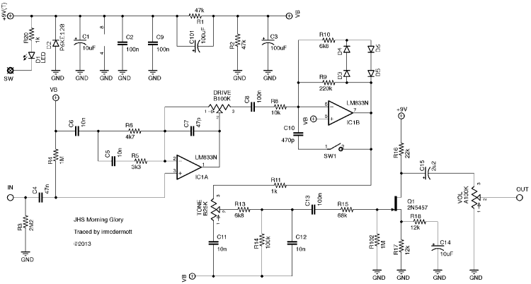
You're correct that the power filtering for the half-rail is non-standard. Generally you'd have C1 and C3 to filter high freqs from V+ and VB, respectively. C101 looks like it would feed the V+ noise directly into the VB. I'd test it with and without C101, and predict that it will be quieter without it.

The only other pedal I can recall with a similar arrangement is the ESR graphic fuzz, but that's a noisy monster and it's so far from standard best practices that it's in the same territory as Devi Ever and DwarfCraft.

In any case, this is just a noise filter for the power supply. You're free to revise that as you wish without much impact on the sound of the pedal. None of those components are in the signal path. I usually impose my own power filtering in my builds, and take whatever's in the schematic as an initial suggestion at best.

As far as which schematic or pedal version corresponds to the layout you linked to, I'm afraid I don't have that information. Presumably mirosol does, though. You might message him directly if he doesn't see this thread.
Reply | Threaded
Open this post in threaded view
|

Re: Morning Glory Schematic Question...?

DogBox
In reply to this post by induction
Hey Induction,
Borrow this from diy.stompboxes site as it works: http://music.codydeschenes.com/wp-content/uploads/2013/05/JHS-Morning-Glory-Schematic.png 
I haven't been able to find any other or the exact one Mirosol used in this reference: http://tagboardeffects.blogspot.com/2013/05/jhs-morning-glory.html 
 From the parts used, they seem to pretty-well match up - except for that paralleled RC! I was going to try and message Miro on his website or IVIark (Mark) from here but thought it could be worth informing others who may not have seen this configuration before either...

Kind Regards,
DogBox
Reply | Threaded
Open this post in threaded view
|

Re: Morning Glory Schematic Question...?

DogBox
Any time I see a pedal made or suggested to make/copy, I always try to look at the Schematic, as I think that it shows how the thing works. I'm still trying to make sense of it all in my old age learning but not quite got the hang of knowing what I can change where to change the voicing of the circuit.
I've found G.G.G. a really great site and JD really easy to talk to. Have a little collection now of his! Still wanted to get into the 'Perf-Board' builds, as they seem really cool like a "point-to-point" amp build crossed with a PCB! All helps the learning curve...

Kind Regards,
DogBox [Steve]