My First Vero Layout (Am I doing it right?)

classic Classic list List threaded Threaded
4 messages Options
Reply | Threaded
Open this post in threaded view
|

My First Vero Layout (Am I doing it right?)

Ciaran Haslett
Hi all.  Trying to get my head around converting schematics to vero layouts so I took a shot at the Darkside (Cornish) buffer from Madbeans Darkside Project while referencing Marks layout here.  This is my first attempt at a layout and I'm asking all you experts if i'm on the right track.


Here is the link to the scheme for reference
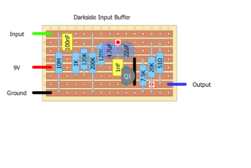
http://www.madbeanpedals.com/projects/Darkside/docs/Darkside_ver.2.pdf

This was drawn just from the boxed Input section.  My confusion is focused on the Collector of Q1.  Both it and the 120K resistor are connected to the supply rail but from the schematic Q1 and the 120K are not connected together.  If both are required to connect to 9V then that must mean they connect together too??  I think its the shorthand style of schematic drawing thats throwing me off.

Can anyone shed some light?

Cheers
Reply | Threaded
Open this post in threaded view
|

Re: My First Vero Layout (Am I doing it right?)

IvIark
Administrator
Yes you'll often see that in schematics.  If you look at it, it would be very difficult to show them physically connecting to the same point because it would make the scheme look like a plate of spaghetti.  So in those instances you just take it as read that those are both connecting to the same point.  It the same as when you see a ground symbol used in more complicated circuits.  It just makes the scheme easier to draw than having to work out how to get them all connected to the same line without making the whole thing look more complicated than it needs to look.

And the rest looks ok except the top connection of the 200K need to be one row lower.
Reply | Threaded
Open this post in threaded view
|

Re: My First Vero Layout (Am I doing it right?)

Ciaran Haslett
Great Mark thanks!

In my learning I have been studying basic electronics where the schematics have been drawn without shorthand symbols with all connections made.  Glad to know I wasn't too far off.

As for the 200K, its amazing how easy it is to misplace a component as it so obviously doesn't connect to ground in the schematic.  You rightfully deserve every credit considering the size of some of the layouts here.

Thanks again for the explanation and the blog.  Inspiring stuff!
Reply | Threaded
Open this post in threaded view
|

Re: My First Vero Layout (Am I doing it right?)

Ciaran Haslett
input....i meant input haha