My first board sans the wiring
12


12
|
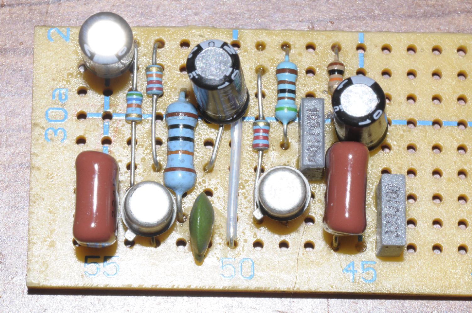
Here's my first board. Excuse the hair, I can;t see it with my crappy magnifier, but my camera picked it up no problem. LOL. Just waing for the mailman to deliver the wire so I can continue.
|
Re: My first board sans the wiring
|
Ahem... let's see the solder side.
|
|
In reply to this post by knight_yyz
what are you building?
as long as your tracks are running left to right and not up and down you've done better than my worst build. it was an ibanez standard fuzz too not some easy and basic one tranny fuzz. a world of pain. c'mon knight, let's see those tracks shine... |
|
I smell a fuzz. Germanium tonebender I suspect, I'm not sure, I've never bothered to build one of those. Also a weird assortment of different types of resistors. Just look at that giant 1K in the middle. It's friggin' HUGE!!!
|
Re: My first board sans the wiring
|
It's a Zvex Mastotron.
Here's the back side... 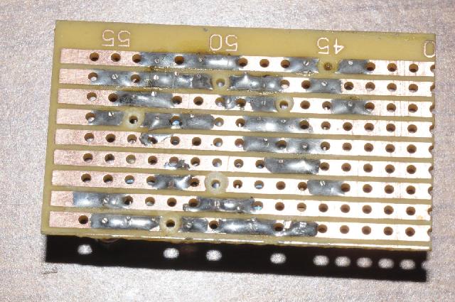 Here's the offboard stuff i can do for now. I'm waitng for my 3pdt boards with the bigger holes, or the pcb style 3pdt stomps, whichever gets here first. Turns out I have a bunch of wire from when I used to do car stuff. Ran out of black ages ago though. 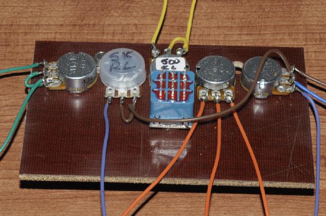 And yes the 5k pot has the wrong lugs and i have to touch up the solder joint... |
|
congrats on a pretty tidy bit of soldering. i thought you were a beginner? you make me look shabby.
only thing i would say is socketing transistors is a pretty good habit to get into early on. that was some great advice i got from fsb for my first build. and lucky because i initially got the pinouts wrong. having sockets made it an easy fix. does it run? |
Re: My first board sans the wiring
|
I guess I am a beginner at vero, but as I have said in other threads, it's not my first time holding a soldering iron.
My first job out of highschool years ago was soldering the wiring harnesses on the gyros which are used in the guidance system of the cruise missile and some airplanes. Had to be done under a microscope. Soldering is easy for me, reading schematics etc is out of my league. I've done piggy back ECU's on cars, hard wired led's into cars with lm317's to limit current to exactly 12v so I have some very basic knowledge... I'm waiting on the 3 position dpdt switch and a few minor components to get this one done. |
|
you can bypass (jumper) the 3pdt just to get it working. just connect input to input jack and output to output jack and forget bypass. be annoying to wait for the 3pdt and then realise there is a problem with the board you could have fixed in advance.
re your soldering, that's clean style. that's what i aim for but don't always get. as to your previous employment, i think it's a wise move by the american military to entrust the soldering of the guidance systems for their nuclear warheads to high school leavers in their first job. and i suppose from there you were able to work your way up to refilling the toner in the office photcopier and running the secret santa at christmas? how will i ever sleep again??? |
Re: My first board sans the wiring
|
Ha! I was eventually promoted to working on a special display for the Canadian F-18's. There were 4096 Led's per square inch on that sucker, but I did the offboard wiring.
I'll try hooking it up if I get the chance this weekend. I also find that having the right gear helps. I have a Hakko F-888 so I can set the temp to where I need it. Up to 850F which is great for doing guitar pots. And I have 3 or 4 different tips I can use. |
Re: My first board sans the wiring
|
Hey knight.
A friendly word of warning.... It looks to me that you have positioned your footswitch sideways. The lug holes should run north/south. Obviously the switches rotation doesn't affect its actualuse but it will affect how you wire it up depending on what diagram you are following. Believe me, I know  And as said, try to get into the habit of socketing the components that make most difference to a pedals operation (trannys, diode, ICs, some biasing components, in/out caps etc). The more you make the more familiar you will become with what does what. Remember, building a clone is good. Building a clone custom voiced for your specific gear and taste is better!  Good luck! |
Re: My first board sans the wiring
|
At this point in time I could care less about the orientation of the foot switch. It's a mock up on a piece of phenolic to see how much room i will have. I am waiting for the proper match up of 3pdt daughter board and foot switch pin type. I have 4 daughter boards from pcbboard.com, but they are made for pcb pins. I don't have any pcb foot switches in my possession. I have 5 boards coming that have the larger holes for the lug style, and I have foot switches coming with the pcb pins. Whichever gets here fist is what I will go with. And again, as long as I put it on the daughter board correctly, orientation means squat.
And where do you get sockets for transistors? Most of them have offset legs, but I can't find anything with offset legs. All I can find is double rows of 3 or 4 or 5 etc... Single rows you can cut, but there doesn't seem to be one for transistors that I can find. I put this on a mock up board so I can put the components in the exact position they will be inside the box without fighting the walls of the box, I can cut my wires to the exact length plus a tad for wiggle room. When I am done it will all fit neatly inside the box with no fuss. it will be 100% soldered and spaced within .005" . Saturday I will be drilling the holes for the box on a milling machine at work. In a week or so I should have my transfer material and waterslide materials and I can experiment with the box graphics. |
Re: My first board sans the wiring
|
Happy days.
Those PCBs make switch wiring a breeze. I'm pretty sure most of us here just use SIL sockets for transistors, diodes etc. I just cut off however many I need. A lot of the layouts here are drawn with the transistor legs in a straight line simply to keep the size down. That usually means bending the offset leg on a TO-18 package transformer. So a properly spaced TO-18 socket would probably give you more hassle as the layout will, more often than not, have the pins in a straight line and no free space around them to accomodate a TO-18 offset socket. Looking forward to your final build. |
|
In reply to this post by knight_yyz
hey knight, i use this stuff and cut it into threes for trannys. as ciaran mentioned, just bend the offcentre leg in line with the rest. almost all the layouts on here (and elsewhere) have the three legs in line.
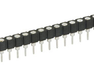 http://www.bitsbox.co.uk/index.php?main_page=product_info&cPath=225_230&products_id=1648 bitsbox is uk based. great service and good prices. maybe someone here can recommend a good place stateside? |
Re: My first board sans the wiring
|
This post was updated on .
I ordered a bunch of those but they haven't come in. I know i have seen the sockets made for transistors, but i guess they stopped making them a while ago.
BTY I'm in Canada. I was able to snag a pile of 14 pin sockets from work. I tried cutting them up but they shatter like glass. I ordered an assorted bag of double row sockets and 3 or 4 rows of that female breakaway style. |
|
Administrator
|
They still make the TO-18 shaped socket but they usually cost >$1 each which costs more than most transistors themselves. So it makes a lot more sense to use SIP sockets or a breadboard
|
Re: My first board sans the wiring
|
In reply to this post by knight_yyz
By the way - it looks like you are running on spare parts, so I highly recommend a set of 1/4-wt metal film (1% tolerance) resistors like this: http://www.amazon.com/Metal-Resistors-Assorted-Values-1120pcs/dp/B00GSPKWMW/ref=sr_1_13?ie=UTF8&qid=1438387748&sr=8-13&keywords=resistors
and save the 1/8-watt ones for the situations where you need to fit one between just two or three rows. Nice work - looks real good. |
Re: My first board sans the wiring
|
In reply to this post by Travis
Quick question, Using the code numbers in this photo, assuming i want to see if the switch works...
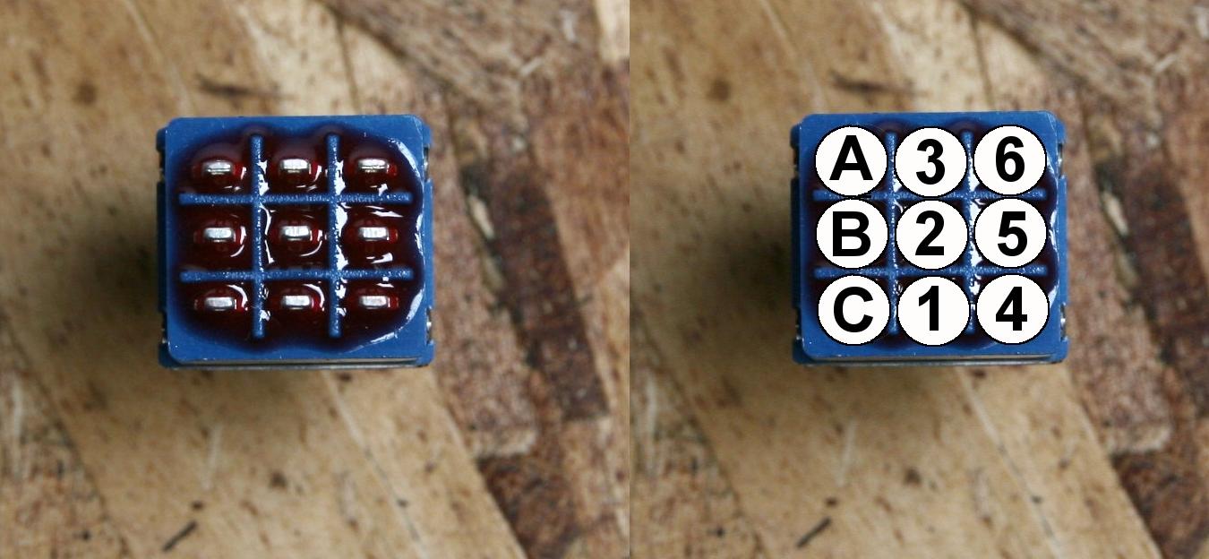 If I place one probe at #2 with the switch in one position I should get 0 resistance on pin 3 and OL on pin 1, then put the probe on B and get 0 on pin A and OL on pin C, and put the probe on pin 5 and get 0 on 6 and OL on 4? The hit the switch and it is all the other way around? I'm testing one that is soldered and my readings seem to not work out that way. Unless I read the wrong way to test this. |
|
if you just want to see iff the switch works, set your multimeter to continuity and place one probe to lug 2 and the other probe to lug 1 or 3. my DMM beeps when when there's continuity. if 1and 2 have continuity, 2and3 should not. click footswitch and check 2 and 3.if you have continuity 1 and 2 should not.
repeat for lugs 4,5 and 6 and then 7,8 and 9. you should be good to go. hope that helps. good soldering btw. |
|
ack!!! didn't see your full diagram. I use conventional numbering.
1,4,7 2,5,8 3,6,9 sorry for the mix up. |
Re: My first board sans the wiring
|
In reply to this post by knight_yyz
That way of testing will depend on how the switch is wired up. You could be testing two lugs that are not connected in the switch itself but maybe via the circuit itself for example.
Another explanation would be that the switch is dead. They don't like a lot of heat. The epoxy can melt and dislodge a lug to the point that the rocker doesn't physically connect 2 lugs together anymore. |
«
Return to Open Chat
|
1 view|%1 views
| Free forum by Nabble | Edit this page |

