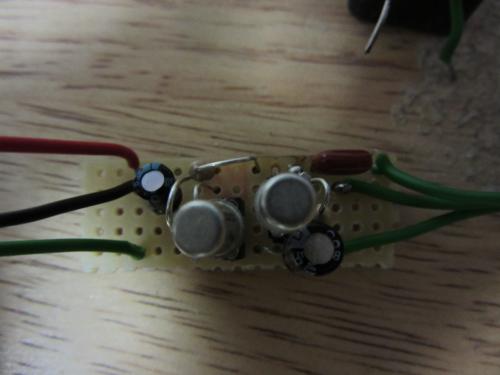
NPN Fuzz Face First Layout

NPN Fuzz Face First Layout

|
Re: NPN Fuzz Face First Layout
|
|
Re: NPN Fuzz Face First Layout
|
|
Re: NPN Fuzz Face First Layout
|
|
Re: NPN Fuzz Face First Layout
|
|
| Free forum by Nabble | Edit this page |