New DIY platform for pedals, feedback needed!

classic Classic list List threaded Threaded
49 messages Options
123
Reply | Threaded
Open this post in threaded view
|

Re: New DIY platform for pedals, feedback needed!

Teemi
This post was updated on .
1. I'll make sure that the jacks fit. If there's too little space between the enclosure and the board, I'll add a small slot in the edge for the open jack collar. There's a deeper slot in between the board mounted jack pins, so that one of the open jack lugs can be about the same level as the PCB. You should be able to drill the jack holes so that the jack won't even touch the PCB, but these slots will help in case you don't have the hole exactly where wanted.

2. I can design specific, marked locations for the pots on the snap-off portion. This will allow me to create a drill template with accurate markings for the potentiometer holes.

If you want to have board mounted jacks, they must be the long pin, straight angle versions, to match the footswitch height. They are not too easily available. But I came up with an idea for that snap-off part: If you snap it off, you'll have a nice daughter board for standard board mounted pots! I'll make sure that it accepts standard pots with 5mm spacing, including stereo pots, and pots that have 2.54 mm spacing, like 9mm alpha pots.

Are there any other pin spacings I should consider? It shouldn't be too hard to design the daughter board to have even weird pin spacings, like 3.75 mm in 12 mm Alpha pots. They can be on the opposite edge of the board, so you just rotate the board to correct orientation to match the potentiometers you want to use.
Reply | Threaded
Open this post in threaded view
|

Re: New DIY platform for pedals, feedback needed!

toddvirgil
Teemi, I'd buy 10 of these right off the bat, especially if we get some layouts going for it.
Reply | Threaded
Open this post in threaded view
|

Re: New DIY platform for pedals, feedback needed!

Teemi
In reply to this post by Heath
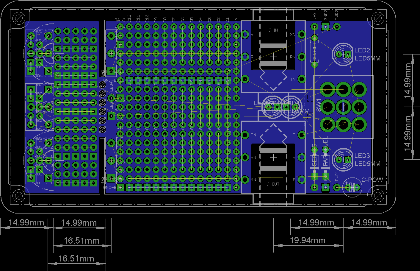
Here's a snapshot of WIP. Nothing's routed yet, nor are there pretty, rounded corners or clear labels. (I'll make sure that there are enough labels, lines and boxes so you can follow it easier when it's ready.)

The top is now snap-off, and on the other edge are my "multi-pot" footprints that accept both 16 mm and 9 mm mono and stereo potentiometers. Each strip next to those pots are connected to a pin, but if you are not using the part for pots, they can be used just as regular pad strips. I gave up the idea of adding other potentiometer footprints in the other end of the snap-off, as it would have made routing a bit too challenging. I might change that, but I feel that the extra area for circuits is more important.

The drill size is 1 mm, except for 1.2 mm the pads for wires.

Mounted jack holes are 1.4 mm. If you use open jacks, you can use the same pads. If the ground or sleeve lug goes on the direction of the board, it fits easily in the cut out slot, and the T pad is on the same side as the tip lug it should connect to.

There are two pads for power, +9 and PWR. PWR is directly connected to power busses, but +9 goes through the SERIES diode. If you wish to use a RC network, you just use a small resistor instead of the SERIES diode.

Reply | Threaded
Open this post in threaded view
|

Re: New DIY platform for pedals, feedback needed!

Philster
That is cool! Personally I love the switch/sockets end but would prefer the whole top end to be vero - if you can get 22 x 22 then that covers a heck of a lot of vero layouts?
Cheers
Phil
Reply | Threaded
Open this post in threaded view
|

Re: New DIY platform for pedals, feedback needed!

Teemi
Technically it would be possible to have at least 22 by 22 pads, and the board would still fit in 1590B. One restriction I have here is the maximum dimension of the PCB. If I make the board wider than 5 cm, the price jumps to next category, and I'd have to ask about $6/pc. The largest practical pad count with this width is 18, although 19 could be squeezed in.

I could make a pure vero stripboard with jacks, 3PDT pads and RC/diodes for power, that would have the copper tracks exposed between the tracks so that you could cut them as easily as with standard vero. I will consider making that after this project.
Reply | Threaded
Open this post in threaded view
|

Re: New DIY platform for pedals, feedback needed!

alltrax74
I agree a vero board would also be nice
Reply | Threaded
Open this post in threaded view
|

Re: New DIY platform for pedals, feedback needed!

Teemi
I did some more research of the fabricating services, and making the board wider and taller wouldn't add to costs so much as I thought it would.

So, it would be possible to change this to an extended vero board. I would put a ground rail on one edge, and power rail on one edge, and in the middle would be at least 13 rows of 19 holes, with copper tracks exposed for easy cutting. On the snap-off there would be no rails on the edge, but additional 9 rows of 21 holes. The price for this larger PCB would go up to only $4 (+taxes for EU citizens).

I think using the already existing layouts would be way easier with the vero style design.

EDIT: I couldn't embed a poll directly here, please vote for your favourite option.
Reply | Threaded
Open this post in threaded view
|

Re: New DIY platform for pedals, feedback needed!

alltrax74
I voted for "Vero layout as large as fits inside 1590B, $4 is not too much"
Reply | Threaded
Open this post in threaded view
|

Re: New DIY platform for pedals, feedback needed!

cylens
same here
123