No Overdrive with "Ginger"
|
Hello nobody :D,
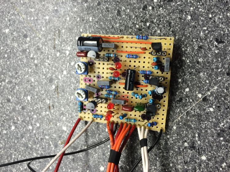
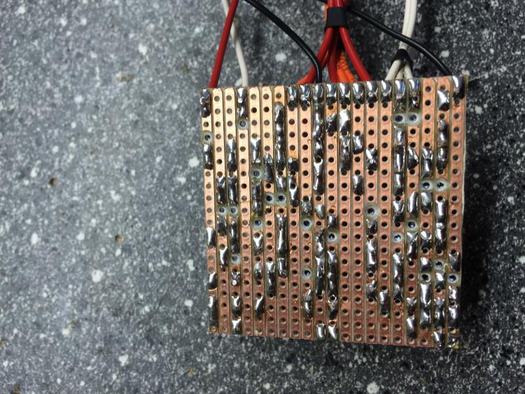
I just recently build a Ginger Bassoverdrive. Everything works great, except, that there is no Overdrive at all. The Gain pot just works as a second Volume control basically. Here some picture of my build. Thanks in advance John  
|
Re: No Overdrive with "Ginger"
|
hi mate.
from your pictures i can't see anything wrong.it's just that cap that i'm not sure.is your 220u orientated correct?if yes then.. maybe check again your cuts-pots wiring-links-voltages... good luck |
|
In reply to this post by Muffit
I have built a few of these, so know the layout is good. All I can say is, put it aside for a couple of days, before going through it again with a fresh pair of eyes. Systematically check everything - cuts, links, component placement, component value, polarity and all your offboard connections.
You have an error somewhere on your build, you just need to track it down. you will know for sure when you have found it - this thing has some serious grind. |
|
HI, thank for your reply, the only thing I did different was that I used 1N5817 except of 1n5818.
Does this make a noticable differents? Cheers |
|
No difference at all I'm afraid, so it's not that.
Like Savvas, I had a quick look at your board, but can't see anything jumping out at me as obviously amiss. I'm afraid it's up to you here, just go through it as carefully as you can and tick off every component and connection. You will find your error - and it will be something minor. It happens to all of us, and more often than most of us would care to admit, so don't get dis-heartend about it. I'm serious about leaving it for a few days though - I have learned to do this when I can't find a mistake on a first de-bugging run through. Put it aside, do something else, come back after a few days, spot the error in two minutes flat. Seems to work every time. It sure saves on tantrums and smashed boards. |
|
In reply to this post by Muffit
Being someone who is in your situation most of the time..
Like the others have said: check for bridges. On your second picture it looks like there's a bridge in the bottom right corner, but it's hard to tell. I checked your components too for a little bit and seems to match the schematic. The only ones that are a bit hard to spot are the diodes/ leds but especially the aformentioned 220U cap. Because it's twisted it's not clear if it's 'direction' is correct. Another thing I have had problems with are: Transistors not locked in the sockets good enough, and a ground wire that wasn't connected (volume 1 to ground says the schematic). This could all be problems that should not result in your problem, but are a part of my checklist. |
|
Thanks for your replies, the 220uf is correct, its just bend weird so it doesnt take up to much space :).
Because I am not that familiar with schematics and stuff, it would be best to check the path of the clipping, correct? So, where is the clipping section of the circuit? is it the LED part or the Transistors? I guess I gonna look over it by tomorrow and meter all components again, look for bridges and get annoyed :D |
|
Good luck!
I always use a very bright flashlight app on my phone to shine underneath the circuit. Makes it very easy to spot bridges (or cuts that have not been 'cut' enough) |
|
In reply to this post by Muffit
Here's my de-bugging process, step by step. I use a different colour highlighter pen to mark off each step on my printout.
#1. I always inspect my solder side first, checking for solder bridges, bad joints etc. Then I double check with a continuity meter, that my cuts really are cut! Then I flip the board over and start on the component side. #2. Check that all the cuts are in the correct place. Mark them off on the layout when correct. #3. Check every component against the layout for positional errors. Put a line through the top and bottom leg holes on your layout printout when you are sure they are correct. I always work in sequence - links first, then resistors, then diodes, then bipolar caps, then electro caps, then transistors, followed by anything else e.g. trimmers and finally off board wire connections, both at the board end and pot or teminal end. #4. Check component values. it's really easy to end up putting a 470k resistor in when the layout calls for a 47k for example, or a 22nF cap instead of a 2.2nF cap. When your are sure they are correct, put a line through the value on your printout. reffer to a reisistor colour code and cap number code chart if your are unsure. #5. Check polarity of diodes and electro caps. Mark on your printout when correct. #6. Check that the pinout on your transistors is correct to the layout. Mark when correct. By this stage I should have found an error, but if everything still looks good, it's time to break out the audio probe. |
|
It's only just occured to me - don't know why I did not think of it sooner, but have you set your trim pots correctly to give 6 Volts to Q1 and Q2 drain? This could be a problem if you have not.
|
|
Well, the Layout of John Kallas says that there should be 4.5V at the Drains of Q1 and Q2,
yesterday I tried to adjust em to 6 Colt but at the Drain of Q2 I was at 5 Volts when I maxed out the trimmer, that shouldnt be like that I suppose. Do you know why this is? I adjusted Q1 to 6 Volts though. Greetings |
|
This post was updated on .
You should be able to get 6V from Q2 trimmer, which suggests a problem between Q1 and Q2.
|
|
Well, I guess I try a different 2n5457. If that doesnt work I know at least at wich point I have to llok.
What are Q1 and Q2 for in this circuit? |
|
Take a look at the layout - they are labelled. Q1 is at top left of board, Q2 top right. (Q3, Q4 and Q5 are along the bottom of the board.)
If you read the last paragraph of the notes on the Ginger page (just above the layout), it says to adjust to 6V. I believe John may have suggested 4.5V, as this is the "standard" voltage setting for jfets. They certainly sound better at 6 Volts. |
|
Definitely try replacing the JFETs. If you max out the drain of one of your JFETs at 5V there is something amiss with the JFET (or perhaps the trimpot). An audio probe would be helpful here as well as your DVM. Good luck!
|
|
Here is what I do with circuits that have a lot of Jfets that need to be biased.
The problem is that if you don't have all the trimmers in the right place you not get any sound at all, or only minimal. So, try every trim pot, and every potentiometer at various settings. Often you will find it was just a matter of one transistor being off because it was not biased correctly. Or sometimes a pot is wired backwards and you didn't notice. Turn all trimpots off (CCW) and bring them up slowly one at a time to see if one gives you any sound. If you hear anything start adjusting potentiometers to see if you can get more sound (maximize it) - then do the rest of the trimpots to see if you can get the maximum amount of sound. This kind of tril and error has made a lot of Jfet circuits work for me, including things like JCM800 with 5 trimpots and seven potentiometers. |
|
I appreciate the comments Paul, but with this one, it's super easy. Using a multimeter, adjust Q1 trimmer until you get 6V on Q1, then do the same until you get 6V on Q2. Check Q1 again, and adjust the trimmer if needed. If so check Q2 again.
That's all there is to it, at least until the pedal is working. It can be fine tuned when boxed up to suit your ears, but to be honest, that should not be needed. This is one of those JFET circuits that just plain works without having to have a big bag of JFETS to pick through to find the "magic" ones, and a week of constant fiddling to dial it in just right. Did I mention that it sounds amazing on guitar, as well as on bass. |
«
Return to Open Chat
|
1 view|%1 views
| Free forum by Nabble | Edit this page |

