No specific effect just a quick Potentiometer question.

classic Classic list List threaded Threaded
4 messages Options
Reply | Threaded
Open this post in threaded view
|

No specific effect just a quick Potentiometer question.

Peter Venkman
I'm just starting to get into using dual potentiometers and I'm a little confused about the pinouts. I know that posts are normally designated as though you are looking at them from the back of the pot, so shaft pointed downward.

My question is when it comes to dual pots and their designation on a layout, which set of lugs are A and which are B?

Seems like it wouldn't matter if you keep the 3 lugs wired correctly to their locations on the board as long as each set of 3 lugs are wired to the correct spots on the board.
make them loud enough to melt the sun
Reply | Threaded
Open this post in threaded view
|

Re: No specific effect just a quick Potentiometer question.

Travis
Administrator
Peter Venkman wrote
Seems like it wouldn't matter if you keep the 3 lugs wired correctly to their locations on the board as long as each set of 3 lugs are wired to the correct spots on the board.
This is correct. As long as each pot is wired properly, it doesn't matter which is A or B
Reply | Threaded
Open this post in threaded view
|

Re: No specific effect just a quick Potentiometer question.

Peter Venkman
Thanks. I actually don't think Im having an issue with the pots after-all. Im working on a Rub-adub-deluxe with the accutronics brick with mod controls, and based on the brick pin out, and the layout on this site, I think something is incorrect on the layout, because of the pin-out on the data sheet for the brick.
The Data sheet shows these connections


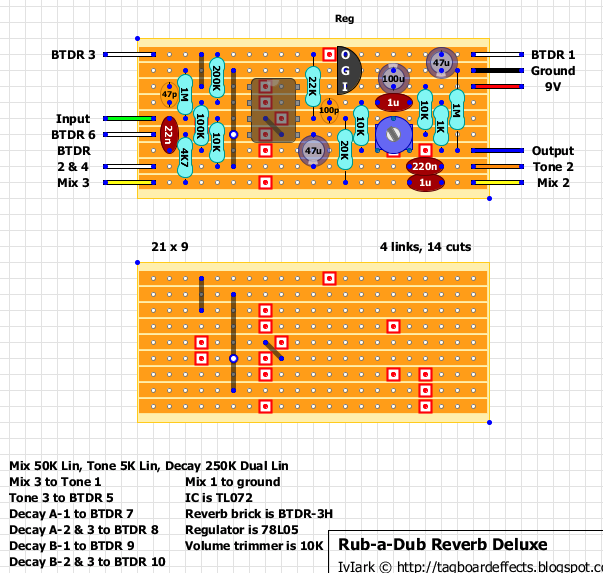
but the tagboard layout calls for these:


Maybe i need to brush up on my circuitry knowledge but it seems like the decay connections are being made incorrectly.
make them loud enough to melt the sun
Reply | Threaded
Open this post in threaded view
|

Re: No specific effect just a quick Potentiometer question.

scimitar
Try as I might I can't see any difference between your 2 layouts? What I can say though is I have build this based on this layout and it all works fine. I think I can see what you are getting at though but it is just a different way of naming the pot lugs - in the data sheet it refers to the 2 gangs of the pot as 1 and 2 and the terminals of each as A & B, this is opposite to the layout on here. If you look at the example circuit it is clearer that they are the same.