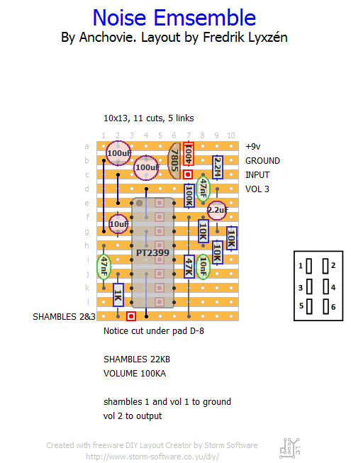
I’m having trouble visualizing how the “loop” switch wires up with the rest of the board. I should be using a DPDT (on-on) switch, correct?
Here is the explanation from parasit studio:
"The loop switch toggles a 3.3M resistor between the input and the output for crazy feedback.
The loop should not increase the volume if it's connected between the input and the volume pot lug 3 (instead of directly to the output). Lowering the feedback resistor value will increase the feedback and vice versa."Can someone help my brain understand how this should be wired? I'm sure it's very easy...I'm just not getting it! i attached the layout along with a numbered DPDT.
Thanks!
