Hi all,
After much reading, research, and having a desire to build for about 15 years, I decided to pull the trigger and do my first build! I chose the BBE Boosta Grande (
http://tagboardeffects.blogspot.com/2013/04/bbe-boosta-grande.html) because it seemed accessible to a beginner, and well, I needed a signal boost!
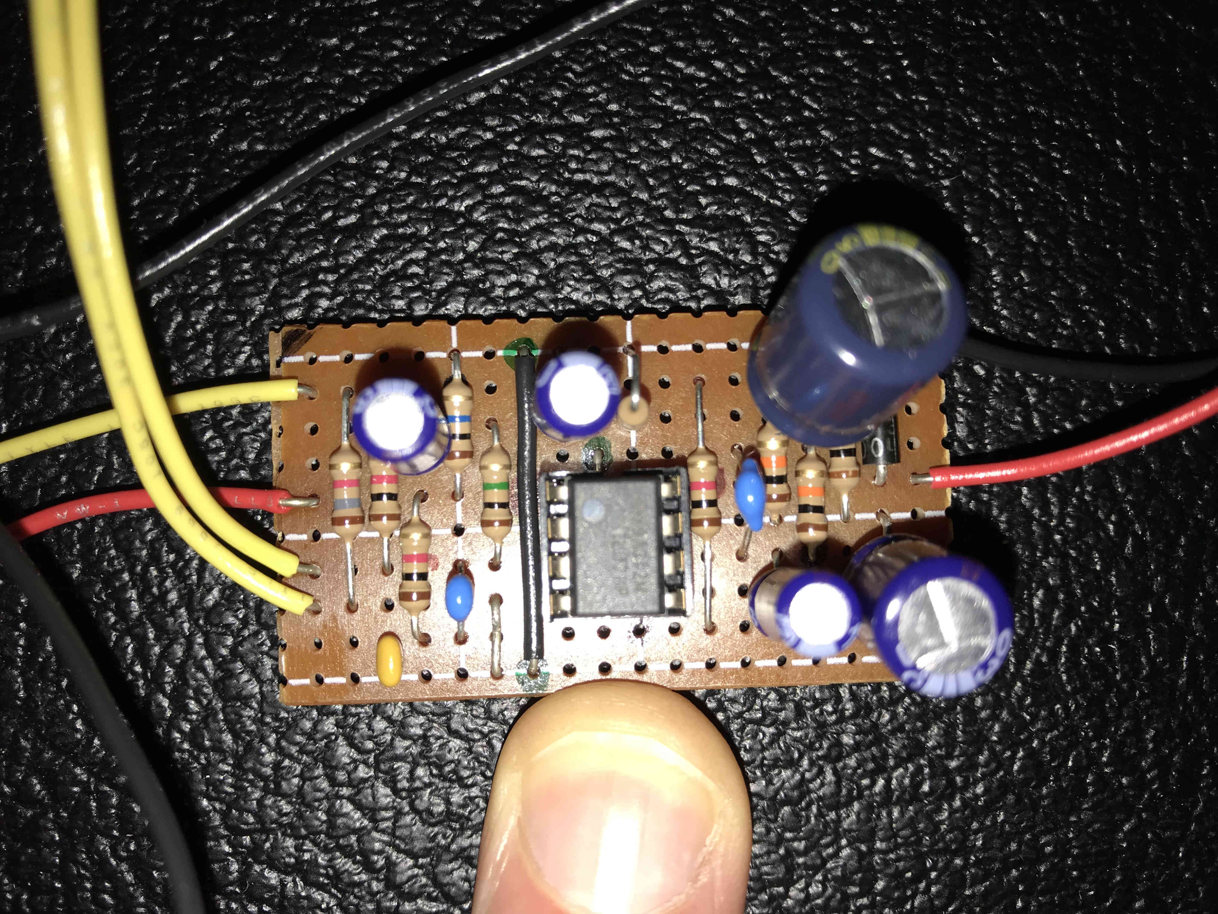
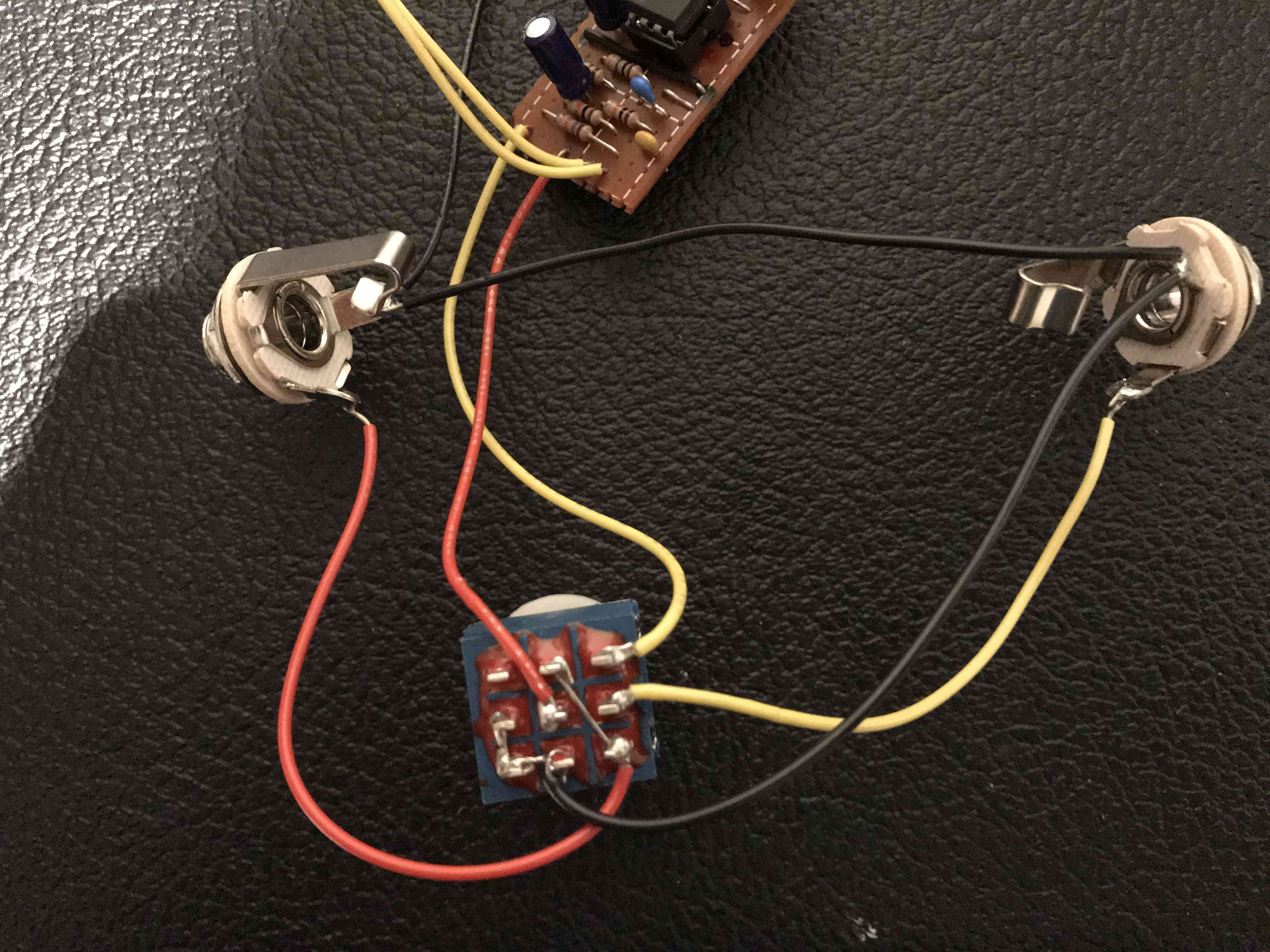
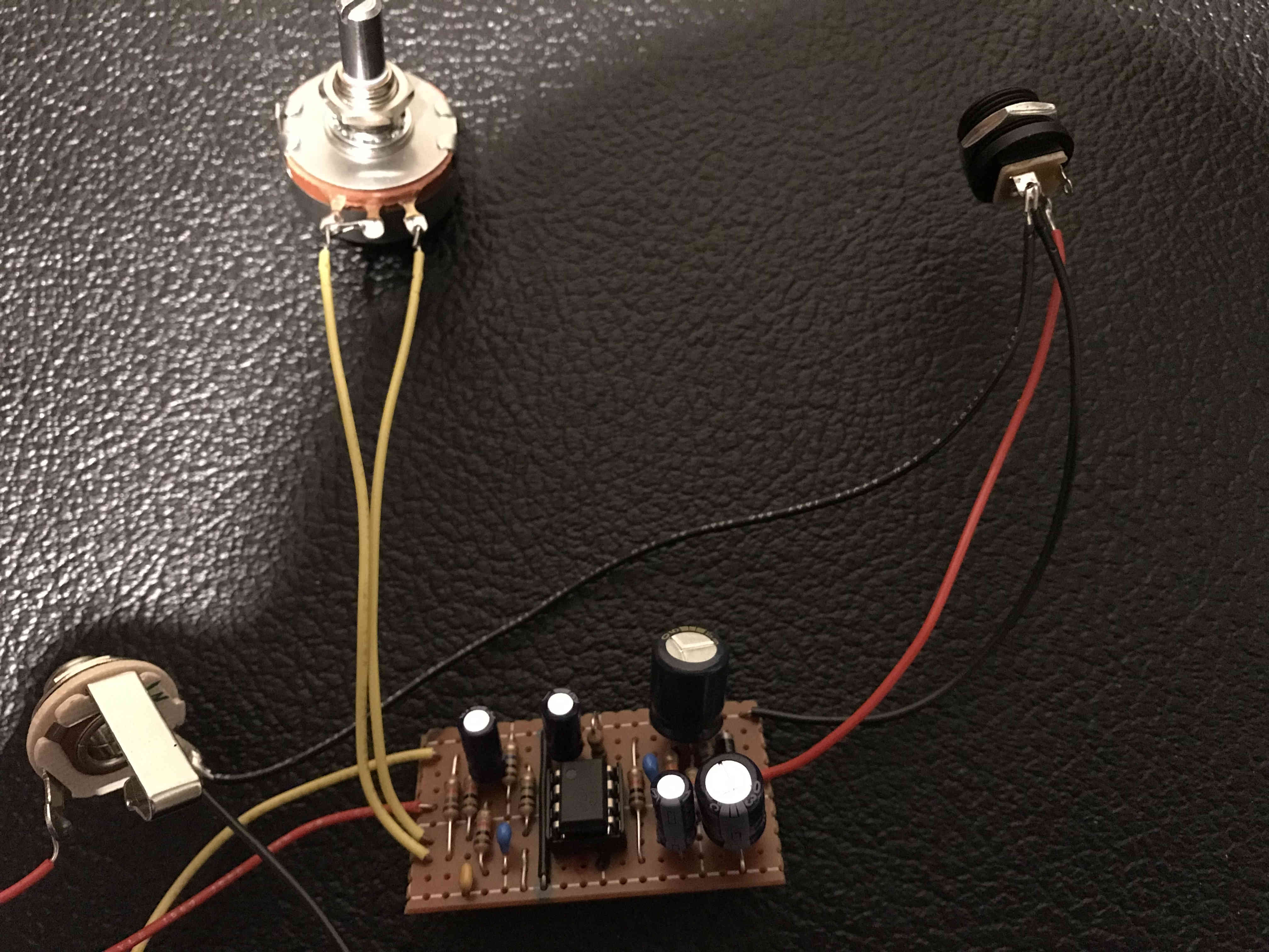
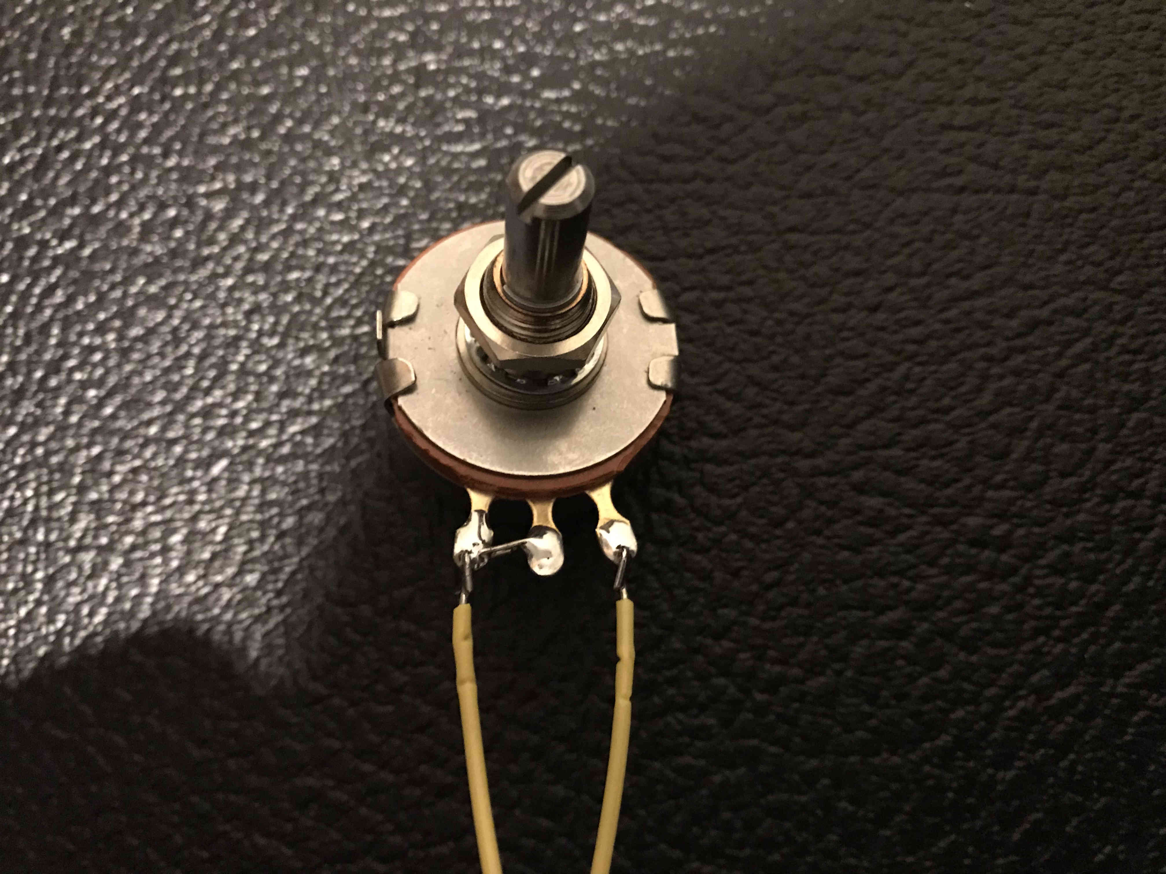
After a few nights of soldering when the kids went to bed, I populated the vero board with all the required components and also hooked up the offboard wiring (per the top-most image, here:
http://tagboardeffects.blogspot.com/2012/02/offboard-wiring.html)
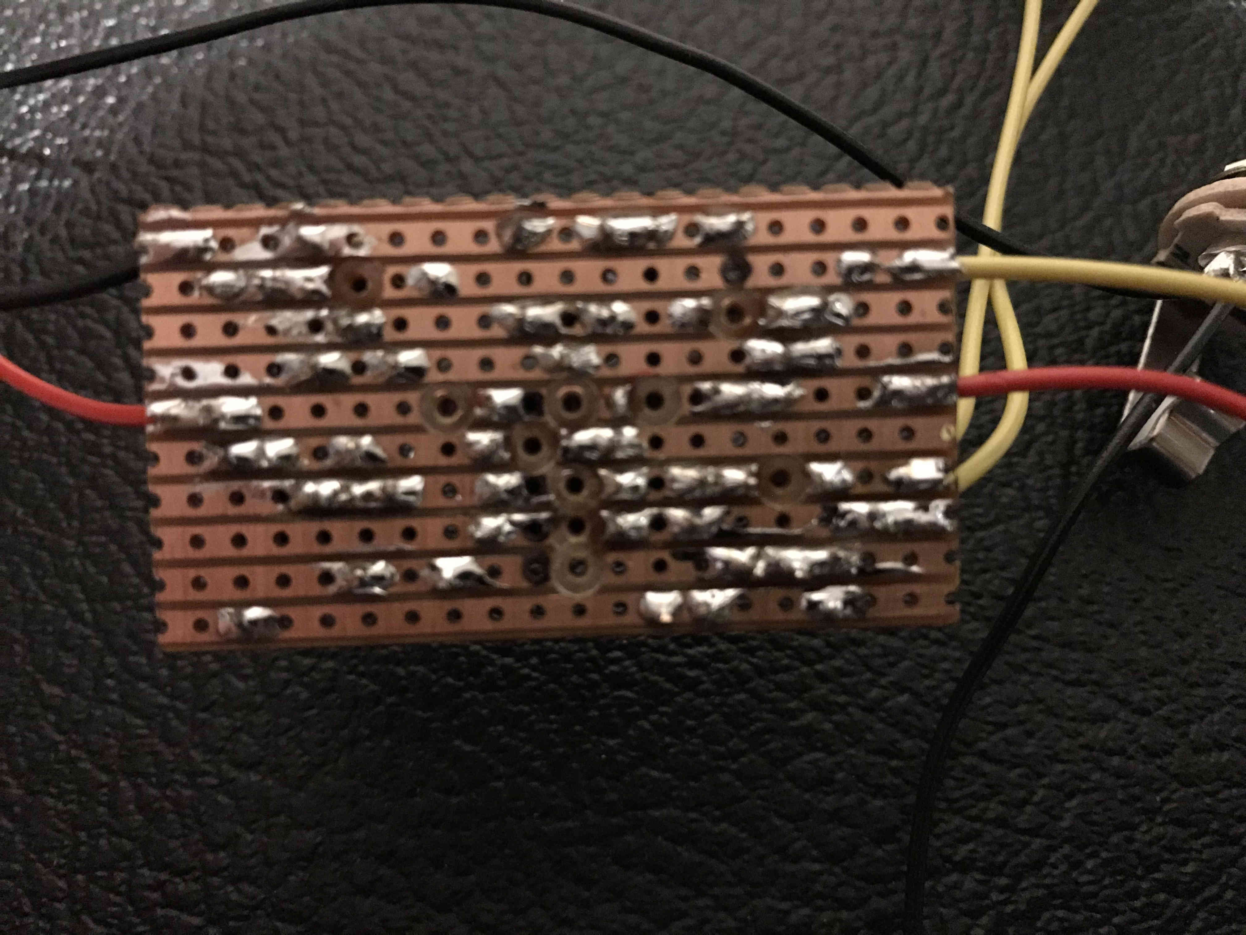
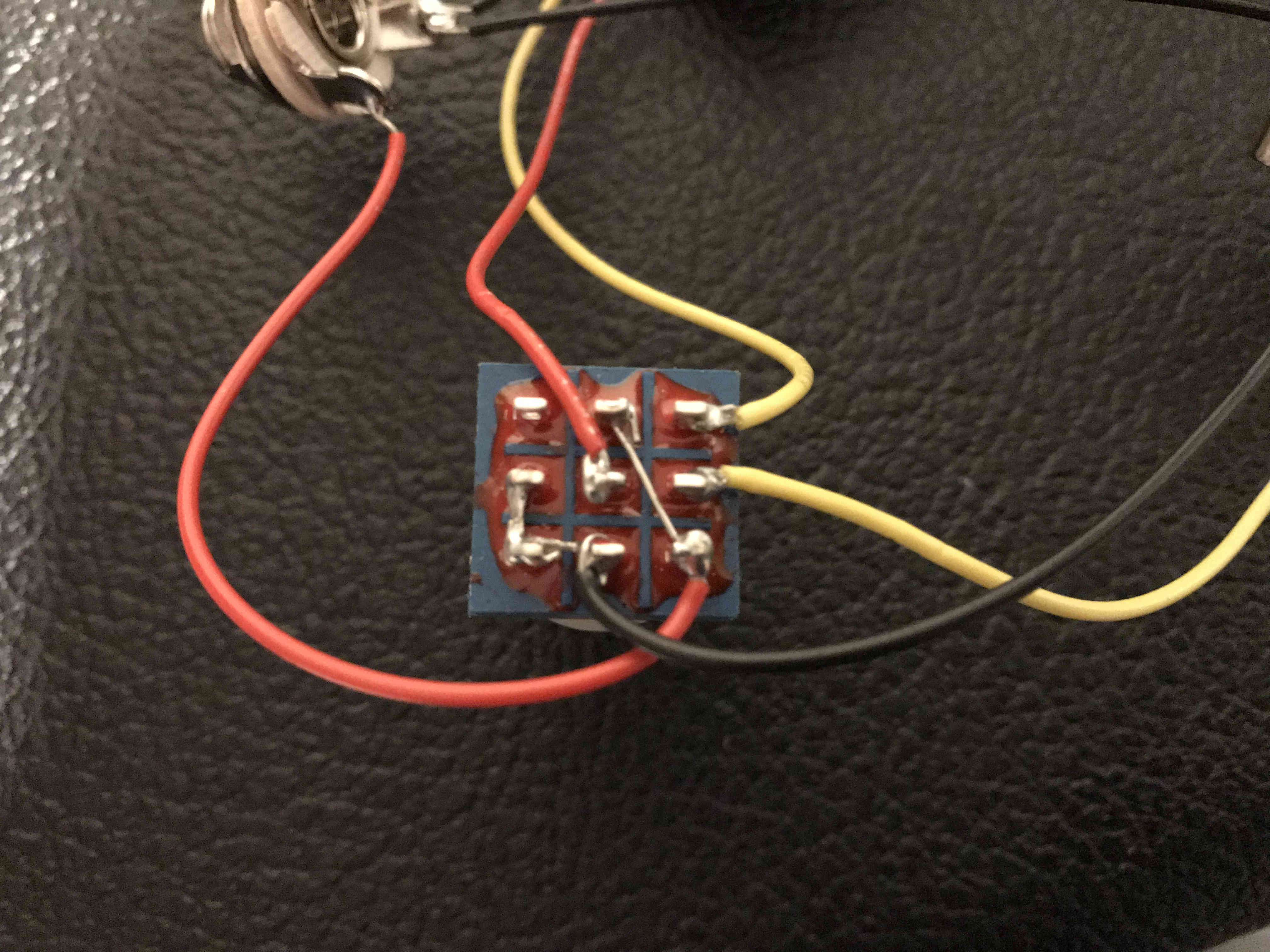
With great anticipation, I plugged everything in AND...nada. I have a clean signal in bypass mode, but nothing whatsoever when the effect is engaged. Pictures attached. I've triple-checked all of my jumpers, cuts, and placements. I verified each individual component to assure they're not faulty, with the exception of the IC (because I don't know how). The IC is placed with the correct pinout (looking at the image in the link above, pins on the left bank 1-4 (top to bottom) and right bank 5-8 (bottom to top). This is the IC purchased:
https://www.digikey.com/product-detail/en/texas-instruments/TL071IP/296-7188-5-ND/378374I checked for continuity where it should not be - nothing. Ran a razor down the channels anyway. No cold solders from what I can tell. I made certain to do all soldering prior to installing the IC.
I am officially at a loss.
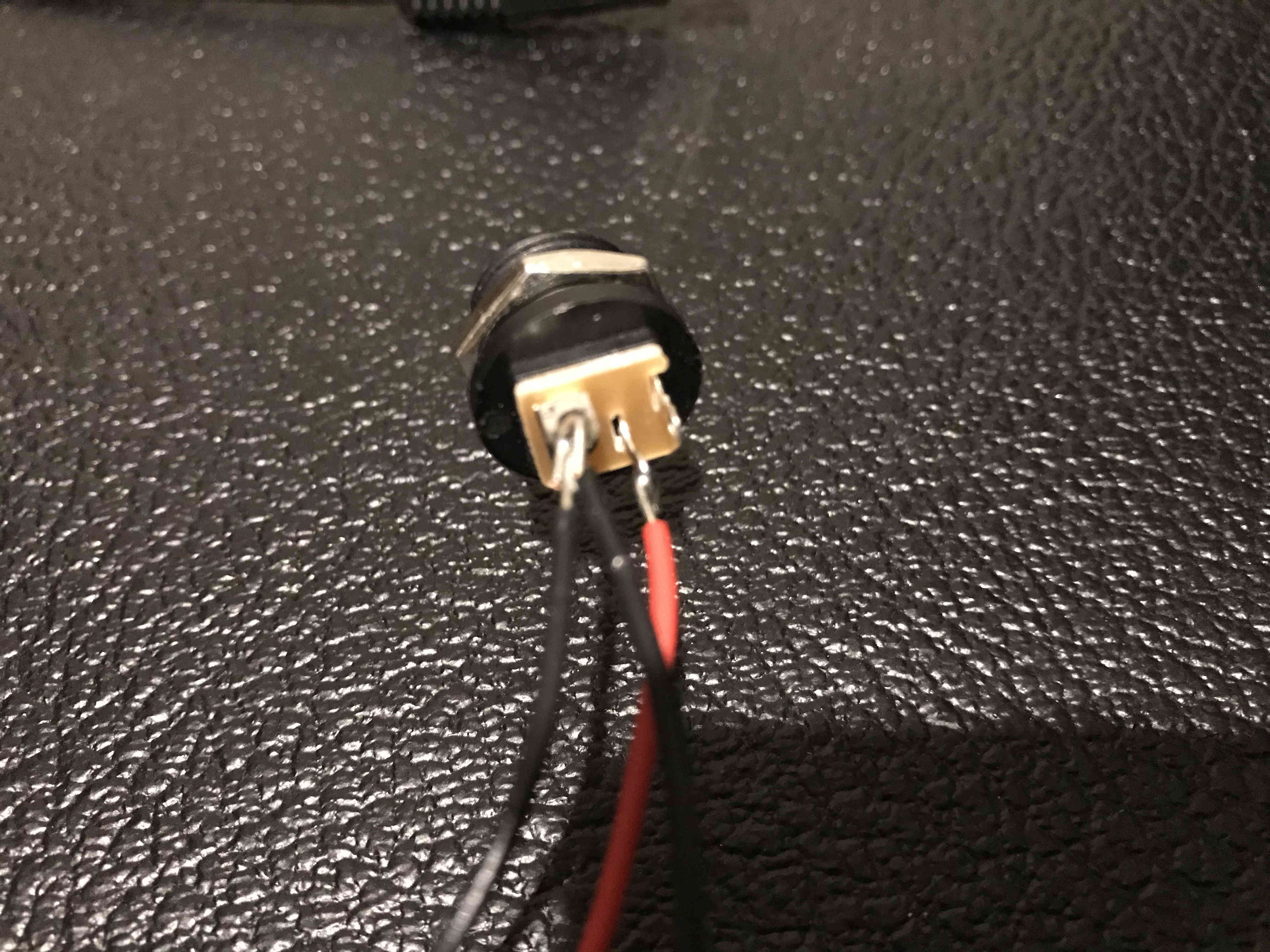
I'm using a Boss PSA power adapter which is center negative/sleeve positive. I opted AC only so no DC battery snap. I have also not yet installed the LED, as I read in the comments it's not necessary right off the bat. I have not yet mounted this in a box, this was a literal bench test. Any help you all can offer would be greatly appreciated - I don't want this hobby to die before it began! If you need better photos or more info, just say the word. Thanks everyone!
I started to think that analysis paralysis has prevented me from the pursuit much. By the time I concluded this, I missed out on even more.

