OD Modifying Help
12
12
|
Hey guys.
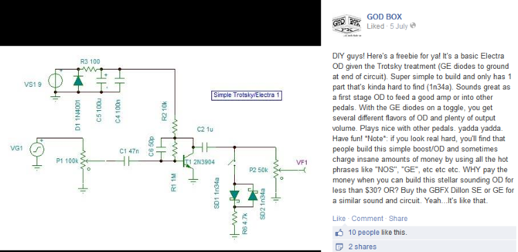
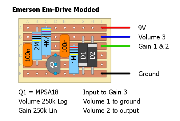
I recently saw this post on Facebook by Godbox FX and it kinda got me thinking.  Could I do this easily to many other ODs? I was thinking about using these diodes to ground with a switch on the Em-Drive if it would work. All in the name of learning. Is this possible? Anyone with better electronic knowledge care to help me out? I want to learn more about how ODs work and modifying/tweaking a simple one seems like a reasonable place to start. |
|
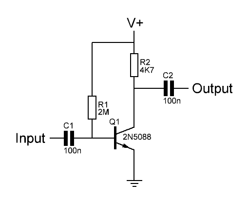
Sure you can. But I don't really know what that 4K7 resistor is for.
Through all the worry and pain we move on
|
|
Yeah, I have no idea. I have a few theories, but I'm too noob to really know.
So I would add the diodes before the volume pot? |
|
Well, there's a lot of places you could put diodes. Diodes in the position described in your OP (i.e. shunted to ground after an amplifier stage output) yield hard clipping. Diodes in the feedback loop of an op-amp (between an input and the output) or transistor (between the gate and collector/drain) yield soft clipping. Diodes shunt to ground at the base/gate of a transistor stop the device itself from hard clipping, which is a really handy little trick (that I make use of myself often).
Let's say you have a circuit constructed like Gain Stage, Clipping Stage, Tone Stack, Output. Generally for a simple hard clipping mod you'd put the diodes on a switch between the clipping stage and the tone stack. I mean, it really depends on the circuit, and like I said, there are so many places you could put them. You could also try Zener diodes and FETs as diodes if you're feeling really adventurous. Jack at AMZ has some great articles about this that are worth a read (Lab Notebook).
Through all the worry and pain we move on
|
|
Awesome info, thanks!
I knew about the feedback loop of an op-amp. I don't really know how it works, but I know a lot of ODs use that method. I have a bunch of different diodes, including zener, so I think it's about time I got a breadboard and started trying some out. |
|
Here is a great summary of how to use diodes in overdrives and distortions. As you can see, there are many possibilities, depending on your desired sound:
http://www.diystompboxes.com/wiki/index.php?title=Simple_mods |
|
Exactly what I'm looking for! Cheers Frank.
Just whilst we're on the subject. Does anyone know what PCB Design software is worth using? Ideally it would be a free one with no licensing shizz. I've seen a lot of guys use one where the board has a lot of pink stuff going on and that looks good, but there are so many to choose from I don't really know where to start! |
|
Ok, managed to get the layout editor functioning (somewhat).
Would this work? I took Mark's layout, added a pulldown resistor and then added the diodes to ground at the end of the circuit. Have I done it properly? 
|
|
Administrator
|
Yes looks good to me
|
|
Awesome! Thanks Mark!
How exactly will this little "clipping stage", if that's the correct term, affect the grit of the pedal? Will the gain pot affect this too? I guess the only real way to find out is to test it, but it wouldn't hurt to know a bit of the science behind it 
|
|
Administrator
|
The gain pot affects the signal level entering the circuit by putting more or less resistance in the way. The diodes clip the signal after amplification and yes it should make a difference, it will be more like a heavy overdrive or maybe even distortion pedal with the right pickups.
|
|
Nice. Do you have the original schematic for the Em-Drive?
EDIT: Also, I presume the pot values won't need changed. |
|
Administrator
|
Well the original was 100K Lin, you'll ned to experiment to see if the differences suit you, I've never tried so don't know.

|
|
Oh, I see. So, the 250k ones were your addition?
|
|
Administrator
|
Aah no actually you're right. 100K was our guess before we knew, they were confirmed at 250K so I'd keep it at that
|
|
In reply to this post by inefficiency
Sonically, the clipping stage will increase distortion and reduce volume. How it works, quickly, is this. In order for diodes to conduct, there has to be a voltage difference across them of a minimum value called the forward voltage (Vf). For silicon diodes Vf is about 0.7V, for germanium or schottky's Vf is about 0.3V, for led's it depends on the color, but it can be in the 1-3.5V range. In a hard clipping stage like the one you've shown but without the 4k7 resistor, anytime the signal exceeds Vf, the excess voltage bleeds to ground and the signal voltage flattens out. (This explains why the clipping diodes have to come after DC is stripped off by a coupling capacitor. Otherwise, all or most of the signal will bleed to ground.) This results in the peaks of the waveform being cut off or 'clipped' (aka hard limited). This is the sound of distortion. The higher Vf is, the more signal gets through, so you get more volume and less distortion with led's and less volume and more distortion with Ge's.
This is slightly different from the distortion you get from the gain stage itself, which results from the transistor attempting to provide output voltage that is beyond the rails. For example, if the input signal is 0.1V and the voltage gain is 100, then the output signal will be 10V plus a bias of 4.5V. The maximum output voltage of the gain stage is 9V, but it's trying to put out 14.5V, so it clips any signal above 9V. The sound of gain stage clipping is dependent on the specific device you use, and sounds a little different from hard diode clipping. Also notable: with gain stage clipping, loudness and distortion increase or decrease together (i.e. louder = more distorted). With diode clipping, loudness and distortion go in opposite directions (i.e. louder = less distorted). The gain control essentially reduces/increases the input signal. With higher gain, the output signal (before the clipping stage) gets higher, so the clipping stage will clip at a different place in the waveform. Increasing the signal has the same tonal effect as reducing Vf, but without reducing the output volume. The lower the ratio of Vf to pre-clipped signal amplitude, the closer you get to square waves. Without the resistor, any signal voltage above Vf will bleed nearly instantaneously to ground until the signal hits Vf. This produces pretty sharp-cornered clipping (lots of high frequencies). Adding a resistor in series with the diodes reduces the current to ground, which means the excess signal won't bleed off as fast, so the clipping edges will be rounded, and the clipping will be 'softer' (less high frequencies, so less shrillness). For more details and fewer simplifications from someone who's much better at this stuff than me, look here. |
|
Wow. Excellent explanation, induction!
I'm thinking after reading that, that it's probably a good idea to add a resistor in series with the diodes. I guess it'll take a lot of tweaking to get it right because I really don't want the mod to affect the transparency of the pedal. I just thought it would be nice to have a little more gain on tap. Despite the tweaking, I think it would definitely be beneficial to put those diodes on a switch. |
|
In reply to this post by induction
Ah, learn something new every day, I had no idea. Thanks, I'll have to try that.
Through all the worry and pain we move on
|
|
In reply to this post by induction
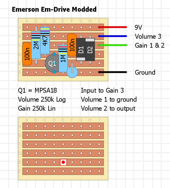
Ok, so it has an ugly standing resistor, but this should work.
Guess now I just need to experiment with what value to use for said resistor. 
|
|
Administrator
|
looks good, just want to make sure that there is a cut to the left of the 47k resistor on the 2nd to last row. if not then that junction is connected to the base of the transistor, which is no good.
|
«
Return to Open Chat
|
1 view|%1 views
| Free forum by Nabble | Edit this page |

