silasmoon wrote
Awesome dude! I appreciate it :) - one question though - what are the tiny red lines in the bottom left hand with the diodes?
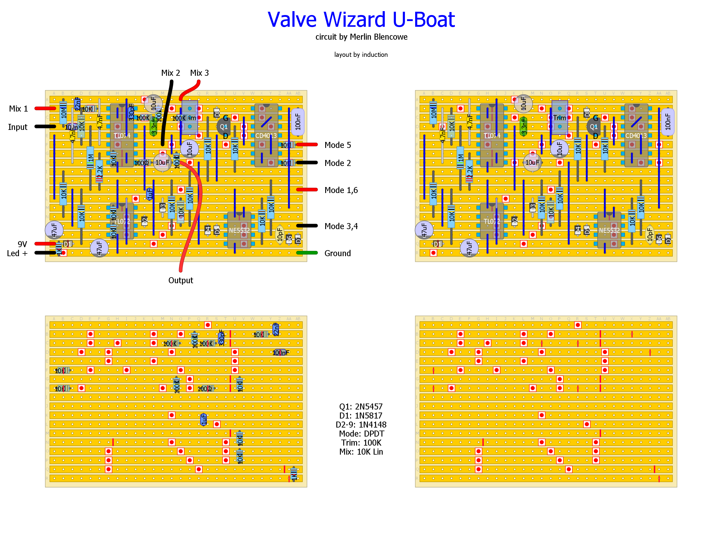
Those are track cuts. The red circles are the standard cuts you can make with a drill bit. The red lines are cuts that need to be thinner. Notice some of the thin cuts are on the holes, and some are between the holes. I use a dremel fine engraving bit to make the thin cuts.
I made this vero for myself and haven't had time to build it yet, so I haven't completely annotated it. The top left image shows all of the components, the top right shows just the thru-hole components. The bottom left shows the SMD components (size 1206, mounted directly on the copper tracks), and the bottom right shows just the cuts. The top two images are shown from the 'top' (the non-copper side of the vero), and the bottom two images are shown from the 'bottom' (copper side) and mirrored from the top images, so they will appear just as you would see them from that side, makes it easier to make the cuts without getting confused. Some of the thin cuts are shown as full-size on the top images so that they will show through the SMD components.
Here's some photos of my build of the Small Time Delay (also by merlinb). It should give you an idea of how to mount the SMD parts on the copper side. Scroll down a few posts to find the layout so you can compare it to the pictures.
If you're not used to this kind of layout (as far as I know, I invented it, so it stands to reason you might not have seen one like this before), it might be a good idea to keep the schematic nearby if you build it and correlate the parts on the layout with the ones on the schematic.
If you haven't soldered SMD before, a kit like
this one is cheap and will give you all the values you'll need for a dozen or more builds. Solder the SMD before the thru-hole components
Here's some easy instructions for soldering SMD (assuming all your track cuts are made already):
1. Lay your board horizontal in a 'helping hands' type of holder. A small vise will work too. In a pinch, you can just lay it on the table, but you don't want it to move. It should be track side up.
2. Melt a small dab of solder on one vero pad.
3. Using tweezers, lay the SMD in position, then use the tweezers to push down on it so it doesn't move.
4. Remelt the solder from step 2.
5. Solder the second pad.
This method isn't quite as simple as traditional vero, but it is surprisingly easy once you give it a try. If this is your first build, I'd try something simpler. But if you've done traditional vero a few time before, give it a try. It's way easier than it looks.