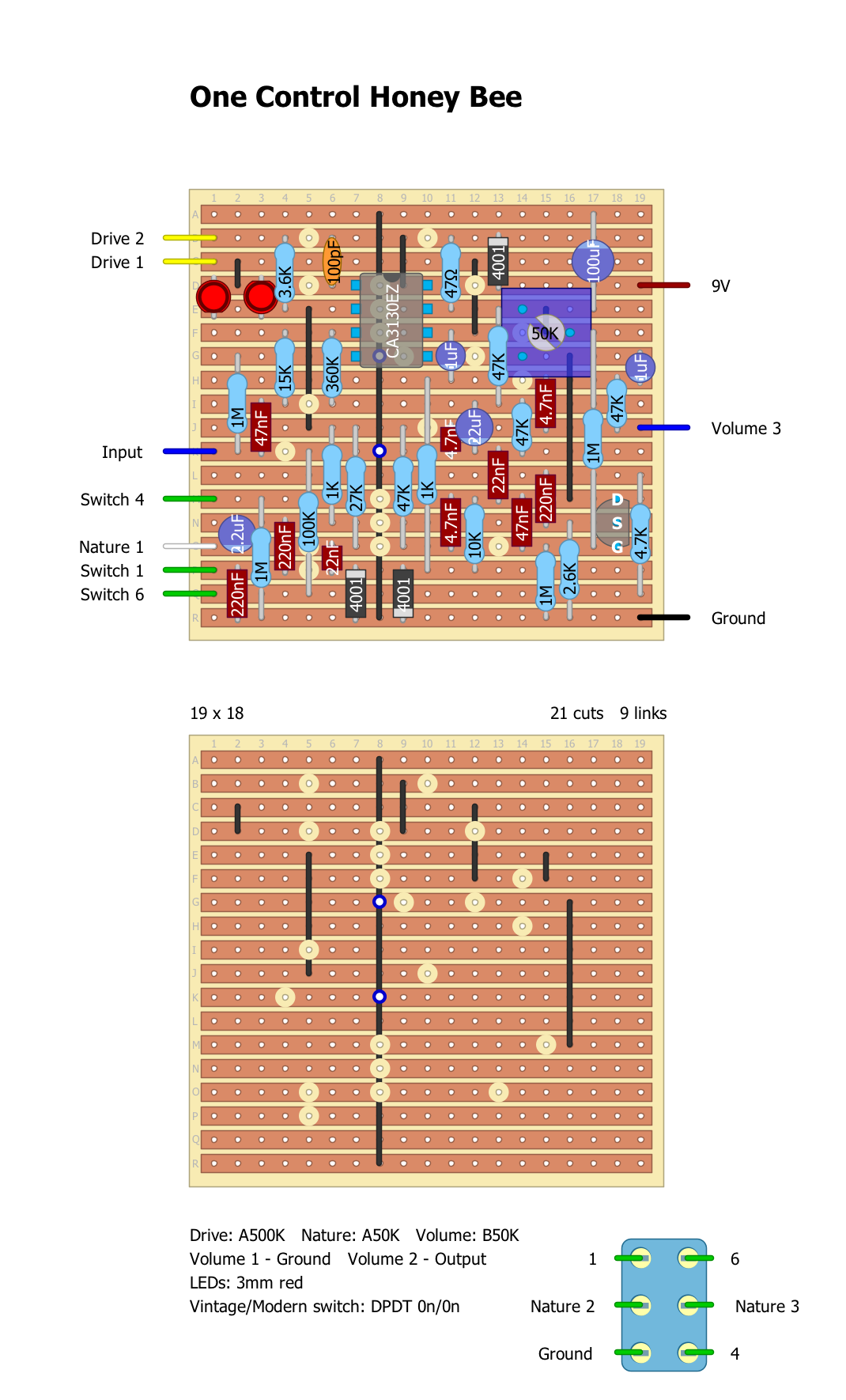
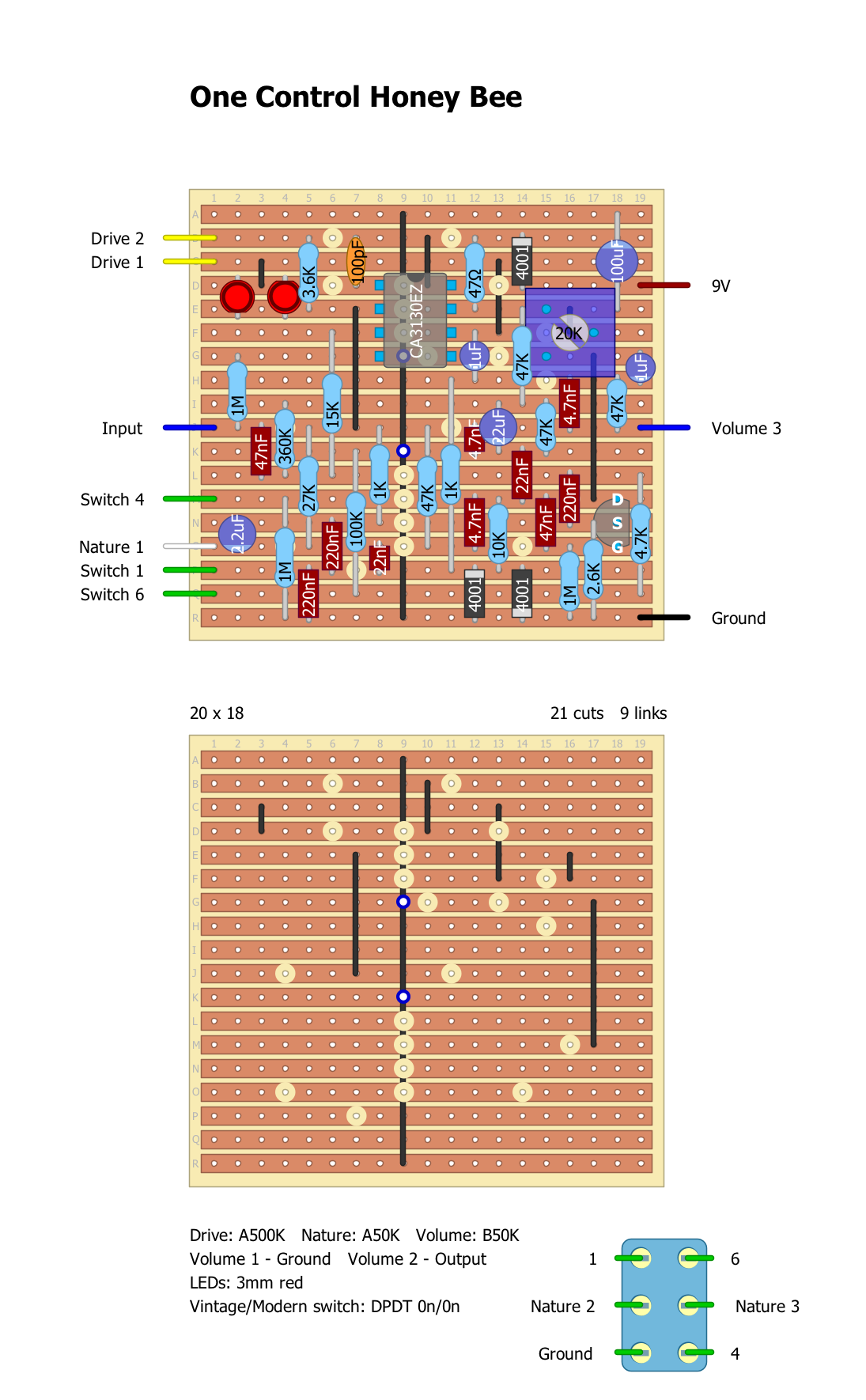
One Control Honey Bee
|
From my interpretation of Daeg's trace of the new Honey Bee. I guessed that the 100n across pins 1 and 8 of the IC was actually 100pF and a couple of other things. I haven't built this yet but have checked until I have gone cross-eyed - this was a tricky one for me and it's not my neatest work. I'll probably build it soon to see if it works.

|
|
Well I have built this and it works - kinda. The controls all work how they should but output is very low. So I must have got something wrong - I have been over this again and again but I can't find the problem. I have tried a few different values of a few components after comparison with older HB circuits but still the low output remains.
Any ideas? |
|
Thanks for the layout!
Have you tried biasing the Jfet? I'm assuming you can use the typical 2n5457 or j201 For these types of circuits, that usually fixed low volumes. |
|
In reply to this post by HamishR
Also, could you change Volume 2 to say "Output" instead of ground :D
|
|
Oops - thanks! Yeah I have tried biasing the Jfet to 4.5V, 5V, 3.7V... Tried biasing it by ear - I used a 20K bias pot which made it easier to do. I only show the 50K because that's what was on the schematic.
I'm wondering about a few values though. I'm wondering if the 22uF to Nature 1 should be 2u2. Not sure about the 47K from pin 2 of the IC either - the schematic shows 147K but the way it's written looks a bit off, as if it's a typo. I have tried 150K, 15K and now 47K but it makes little difference. The next thing I think looks off when compared to an original Honey Bee is the 360K between pin 3 and Vref. On the original HB it goes to pin 3 via the 15K to the input cap. I think that might be worth changing. |
|
hmm... I'm sure you already read this over, but after a quick glance, I wonder if the 50k is just "missing the mark" when biasing due to the massive range?
"-- The Output / JFET Gain Stage is biased unusually. This version adds a 1M Resistor (R15) to V+ which lifts the Gate Voltage to 0.4V. It then replaces the usual 5.6k Drain Resistor with a 50k Multi-turn Trimmer. I would not recommend using this method, and would absolutely caution against a 50k Trimmer if you don't use a Multi-turn. The range of operation is very narrow and I don't know why they did it this way. My unit was tuned somewhere between 6.5k and 7.2k." I also saw the Honey Beest uses a 2n5952 and it biases at the Source. I wonder if swapping your layout to bias at the source and having that 2.6k connect to the drain will do anything? *shrug* you're definitely more knowledgeable than me, but hope I at least get some gears turning hahaha |
|
"*shrug* you're definitely more knowledgeable than me, but hope I at least get some gears turning hahaha
" Oh no - I doubt that very much! I am good at puzzles - that's why I like drawing layouts. But my electronics knowledge is extremely limited. You may have a point about the trimmer. I actually used a 20K to get more accuracy. It will cut out sound when turned too low and get lower as it gets above 6-7V or so - I didn't measure, but there is a sweet spot. unfortunately it's not sweet enough. I have tried moving the 360K resistor to match how it works in an older HB but that made things even quieter. I think I'll put it aside for a day or two and then compare it more with older HBs. I am suspicious of the schematic! I think you are right about the issue being around the Jfet. If I measure the voltages I get almost the same on gate and drain... Actually as I look at it again I am wondering if I should just remove that 1M from 9V to the gate. |
|
Aha! Success! I clipped the weird 1M resistor from 9V to gate and now I have volume. Everything works now - the switch adds/subtracts bass at the CCW end of nature as suggested in the copy. The 20K trimmer works a treat in my build.
Now I want to try the positioning of the 360K resistor. Right now I have it going between Vref and the junction of the 47nF input cap and the 15K going to pin 3 rather than straight to pin 3 as shown in the schematic, because that's how it goes in the HB schematics I have seen. I also have a 2u2 at Nature 1 - 22uF seems a little OTT! I'll draw what I find and repost it. |
|
This post was updated on .
Ok this is what I have so far. I really don't know how accurate it is but it's the best I can do with what I have and it works!
 FWIW I didn't use a 50K trimmer so feel free to use a 20K as long as it has enough range for your Jfet i guess. (edit) I have now tested some more with a Strat (ok - quite low gain of course but a good, full sound and nicely old-school) and with a Gibson with P90s. Wow. With P90s this sounds great. The switch actually offers some useful difference with enough low end in "modern" mode and lots too much in "vintage". Cool! I used a 3 way switch on mine because I had run out of 2-way and strangely enough the middle position is useful too. FWIW I didn't use a 50K trimmer so feel free to use a 20K as long as it has enough range for your Jfet i guess. (edit) I have now tested some more with a Strat (ok - quite low gain of course but a good, full sound and nicely old-school) and with a Gibson with P90s. Wow. With P90s this sounds great. The switch actually offers some useful difference with enough low end in "modern" mode and lots too much in "vintage". Cool! I used a 3 way switch on mine because I had run out of 2-way and strangely enough the middle position is useful too.
So this is definitely verified and a great sounding pedal. 
|
|
Awesome, thanks! Weird about the 1M resistor! A part of me wonders if he threw that in there to throw us off hahaha I know, in the past, he's had some gripes with people stealing his design. Or, at least I remember seeing him in the forums defending his design, etc.
Good to know about that MIDDLE position too! Going to build this one over the weekend! :D :D :D |
|
So how did it go? FWIW after some discussion with Daeg, who drew up the schematic, I have come up with this layout - it's the same except for a 150K where I had a 47K. He insists that the cap at Nature 1 is 22uF and he may well be right, but I'm sticking with 2u2 because it sounds better to me. :-)

|
|
Ah, sorry, finishing up a MIDI project, so didn't have time to box everything up. This one is going in a 5-in-1 pedal, so will take a while haha
Thanks for the follow-up! <3 |
|
I was just experimenting with this pedal today and you guys are not going to believe this - I was interested in what voltage to bias to and what value resistor would work best in place of the trimmer. I only used the modern setting of the switch as that is the setting i gravitate towards.
So i tested the value I had set it on by ear originally and I had 2.7VDC with a resistance of 8.37K. So I thought aha! I could use an 8K2 resistor to bias the transistor. So then i thought I'd try biasing by ear again - see if I could get it to sound any better. So I fiddled around a bit and found a setting I liked even more - and it was almost exactly 5K6 and 4.5VDC! Crazy! It was something like 5K61 and 4.52VDC - that's ridiculous. So I think in future if I build this again I will just use a 5K6 and check it. |
|
Oh, man, you're like improving the circuit more and more hahaha
Thanks for the heads-up! I made that 47k to 150k resistor change last night and am starting the wiring tonight or tomorrow night. Can't wait!!!!!! |
|
Just finished my 5-in-1 with this guy in it! I really like this for the low gain tone! It doesn't seem to have the same amount of gain as the Sweet Honey, but I'm okay with that since I'm using it for low gain.
I'll have to double check, but I biased the drain to 4.5v, changed 47k to 150k, and changed 2.2uf to 22uf. Overall, I'm happy with the layout, so whoever is wondering, just go for it! https://www.instagram.com/p/BrUF1FwHpbk/ |
|
That 5-in-1 is crazy! Too cool!
Yeah the HB is a low-gainer depending on the guitar. It can make a great boost for something like a Strat but it has plenty of gain with a Gibson. If you want a HB kind of tone but with more gain I can recommend the Honey Beest, because that's pretty much what a Honey Beest is. It has an extra Jfet stage on the input and is one of my favourite Strat ODs now. You can make a Strat sound fatter and chunkier which is always something I'm trying to do. With the Sweet Honey I have increased the input cap to 47n and that helps make things sound fatter. I might even try bigger for the Strat. In fact switchable input caps could be a good thing for a Sweet Honey. |
«
Return to Booster, OD, Fuzz, Distortion
|
1 view|%1 views
| Free forum by Nabble | Edit this page |

