Os Mutantes Octaver
|
I have no idea what this is. Found a PDF file online of an article from an old brazilian magazine written by Claudio Cesar Dias Baptista, you know, the guy who did the Os Mutantes Fuzz . The schematic calls for two 9v batteries but I did a vero for one battery only. I have no idea if this will work but this thing looks quite interesting nonetheless.
Schematic info and possible mods here: Mutantes Octaver Vero:  |
|
Interesting indeed!
Thanks for sharing :)
check out my building blog at www.parasitstudio.se
|
|
In reply to this post by anders
It looks nice, Anders.
Cláudio César Dias Baptista, CCDB, is by far one of the most important Brazilian musical electronics developers ever. He started working with musical electronics around 1963 and worked closely with Os Mutantes, the band in which two of his brothers played - Sergio Dias Baptista and Arnaldo Baptista. Unfortunately, CCDB went totally nuts and refuses to talk about electronics nowadays. He lives in a beach city 2 hours far from Rio de Janeiro and spends his time writing about aliens and spiritual beings that live across the universe (or crazy stuff like that). He claims to have created the greatest sounding guitar ever, "Regvlvs". The unit has built in effects and was used by Sergio Dias, who now produces modern copies. Both guitars can be seen in this video: https://www.youtube.com/watch?v=CImCsuKP29Q - at around 0:45 Sergio picks up Regvlvs to show it to the interviewer and explains that he started to produce the copies because the original one has fallen from his hands into the floor and broke. CCDB wrote many articles in a magazine called "Nova Eletrônica" ("New electronic"). This magazine was the main source of information for Brazilian DIYers during decades. It's possible that many guitar effects and projects made by CCDB are still waiting to be rediscovered among the pages of one's collection. Anyways, just a tiny bit about this interesting fellow called CCDB. |
|
In reply to this post by anders
thanks for the layout anders. you've got the freaky shit.
why two 9v batteries in the original layout? is one signal starved and inverted or something and mixed with the other? ccdb is a mysterious one. i'm definitely a fan of those wild card outsiders who reinvent the sonic universe in their garden sheds. joe meek being another obvious example. os mutantes octaver could be the bat macumba fuzz squared. a wasp in each ear. since there are no demos may as well post the os mutantes to give a hint of where it might be coming from. and because go-go-girls make the world go around. actually gets a bit octavey at the end of the track though that's probably just playing in the sweet upper frets. ps. i added a link to this thread and layout at fsb as pinkjimiphoton expressed an interest in seeing a vero layout. hope that's ok. jimi's a hardcore member here too. |
I thought that was a kazoo |
shatner's bassoon?? |
|
Built this a while ago but just got round to debugging. It doesn't work. Fine in bypass but no signal coming through when engaged. Thouroughly debugged so i wonder if the two 9v supplies (batteries) is the issue. Sorry my schematic skills are pretty limited.
"Red velvet lines the black box"
|
|
From looking at the schematic, the reason for the second battery is so that the first two transistors (Q1 and Q2 and components in upper left of the vero) can operate between +/- 9v relative to chassis ground set by the jack sleeves. The emitter resistor networks of those transistors are connected to -9v, not to the ground rail - look at where the 2.2k resistor goes from the emitter of Q2, for example. So the layout as drawn doesn't represent the schematic. It might be fairly simple to fix since there are not many elements that are connected to -9v.
|
|
Ok, that makes sense, thanks. Hopefully someone with better skills than me can work out a fix for this as wouldn't mind getting it working.
"Red velvet lines the black box"
|
|
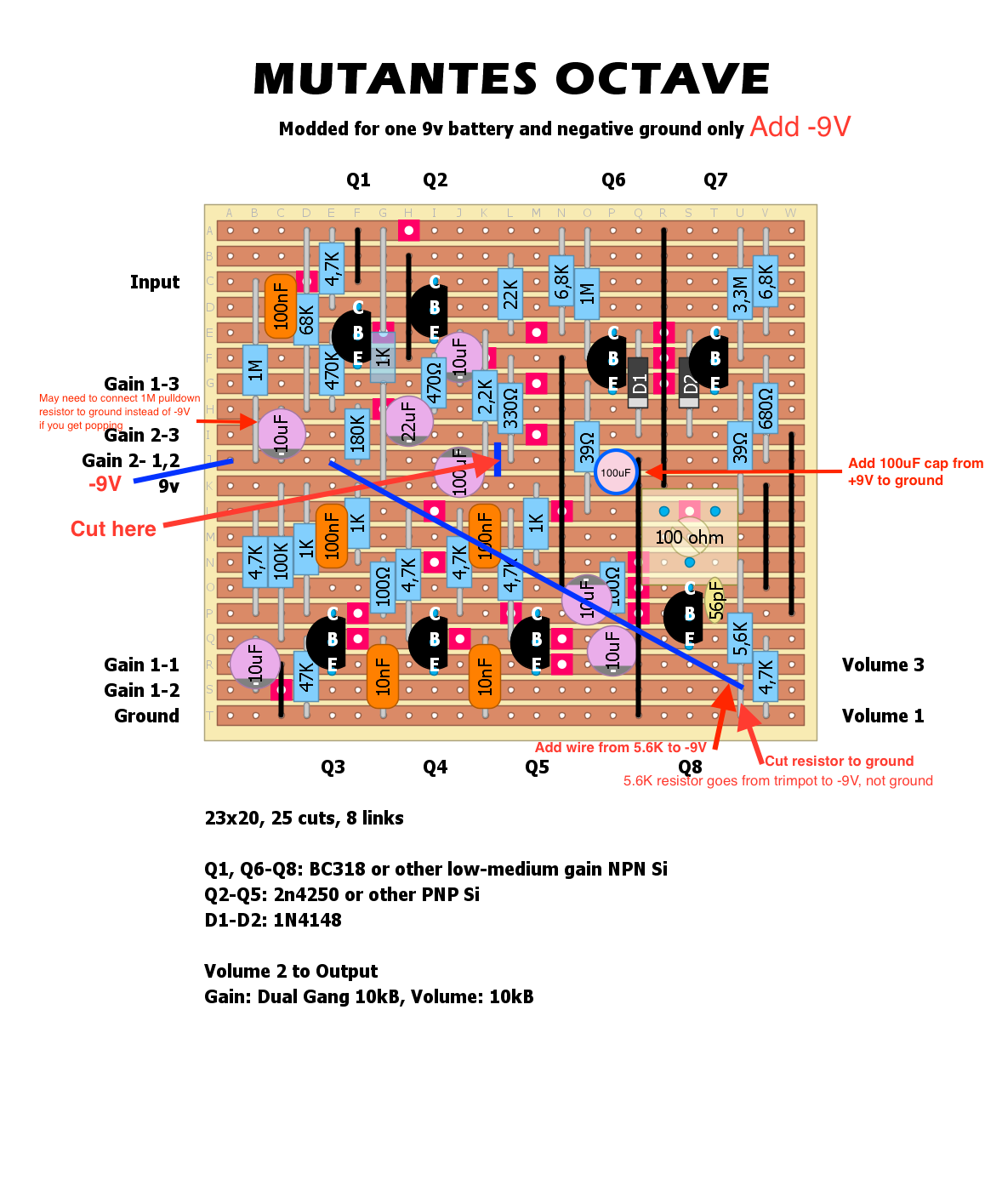
Hopefully this doesn't step on Anders's toes - I've annotated his layout with details on how to add the -9V supply separated from the ground rail. You'll need to cut a trace, add a few wires, and add a 100 uF DC filtering capacitor. Comments are in red text and the cut and added wires are in blue.
There are now a couple of minor deviations - there is a 100uF filtering cap between +9V and -9V, where the schematic has it between ground and -9V, and the 1M pulldown resistor that Anders put in may need to be moved. These shouldn't make a big difference in whether it works or not. 
|
«
Return to Unverified Layouts
|
1 view|%1 views
| Free forum by Nabble | Edit this page |

