Overdrive circuit to vero Request

classic Classic list List threaded Threaded
17 messages Options
Reply | Threaded
Open this post in threaded view
|

Overdrive circuit to vero Request

matthew1234

Could someone please convert this circuit to 9v and put it on a vero layout please and thank you.

Thanks,

Matt

Reply | Threaded
Open this post in threaded view
|

Re: Overdrive circuit to vero Request

jaredcohen
I can do this one. It'll be easy. But, it probably won't sound right, it's meant to run at 15v. So think about which voltage you really want it to run at. You could do 9. Or 18. Or regulate 18 down to 15. Or 12, which is closer to 15 than 9 is. What I'm saying is you should decide that now. Because the vero looks the same whether your power adapter is 9, 12, 15, or 18v. The difference comes if you want the power conversion to happen INSIDE the pedal.

Also, I assume CR1 and CR2 are diodes. Not clear from this what type of diodes they are.
Reply | Threaded
Open this post in threaded view
|

Re: Overdrive circuit to vero Request

matthew1234
Hey, thank you so much for your reply. I basically just wanted to be able to plug in into a typical 9v center negative boss power cable along with my other pedals. 

Thank you so much!!
Matt

On Mar 15, 2018 2:12 PM, "jaredcohen [via Guitar FX Layouts]" <[hidden email]> wrote:
I can do this one. It'll be easy. But, it probably won't sound right, it's meant to run at 15v. So think about which voltage you really want it to run at. You could do 9. Or 18. Or regulate 18 down to 15. Or 12, which is closer to 15 than 9 is. What I'm saying is you should decide that now. Because the vero looks the same whether your power adapter is 9, 12, 15, or 18v. The difference comes if you want the power conversion to happen INSIDE the pedal.

Also, I assume CR1 and CR2 are diodes. Not clear from this what type of diodes they are.


If you reply to this email, your message will be added to the discussion below:
http://guitar-fx-layouts.42897.x6.nabble.com/Overdrive-circuit-to-vero-Request-tp42144p42185.html
To unsubscribe from Overdrive circuit to vero Request, click here.
NAML
Reply | Threaded
Open this post in threaded view
|

Re: Overdrive circuit to vero Request

induction
I just want to point out that the original schematic calls for 15V bipolar. Which is equivalent to 30V unipolar. So at 9V, you're dropping the supply voltage by 70%. Have you breadboarded this at that voltage? It might have a strong impact on how it sounds, like Jared said. Personally, I'd want to hear it before I went to the trouble and expense of building it.

On the other hand, if you build it at 9V and it doesn't sound right, you could always add a charge pump daughterboard so you don't have to mess with the main board after it's built.

By the way, where does this circuit come from?
Reply | Threaded
Open this post in threaded view
|

Re: Overdrive circuit to vero Request

matthew1234
Its the overdrive circuit for the fender frontman amp. I saw it on an online forum.

On Thu, Mar 15, 2018, 7:32 PM induction [via Guitar FX Layouts], <[hidden email]> wrote:
I just want to point out that the original schematic calls for 15V bipolar. Which is equivalent to 30V unipolar. So at 9V, you're dropping the supply voltage by 70%. Have you breadboarded this at that voltage? It might have a strong impact on how it sounds, like Jared said. Personally, I'd want to hear it before I went to the trouble and expense of building it.

On the other hand, if you build it at 9V and it doesn't sound right, you could always add a charge pump daughterboard so you don't have to mess with the main board after it's built.

By the way, where does this circuit come from?


If you reply to this email, your message will be added to the discussion below:
http://guitar-fx-layouts.42897.x6.nabble.com/Overdrive-circuit-to-vero-Request-tp42144p42192.html
To unsubscribe from Overdrive circuit to vero Request, click here.
NAML
Reply | Threaded
Open this post in threaded view
|

Re: Overdrive circuit to vero Request

matthew1234
In reply to this post by induction
Which charge pump circuit would I use and how would I connect it?

On Thu, Mar 15, 2018, 7:32 PM induction [via Guitar FX Layouts], <[hidden email]> wrote:
I just want to point out that the original schematic calls for 15V bipolar. Which is equivalent to 30V unipolar. So at 9V, you're dropping the supply voltage by 70%. Have you breadboarded this at that voltage? It might have a strong impact on how it sounds, like Jared said. Personally, I'd want to hear it before I went to the trouble and expense of building it.

On the other hand, if you build it at 9V and it doesn't sound right, you could always add a charge pump daughterboard so you don't have to mess with the main board after it's built.

By the way, where does this circuit come from?


If you reply to this email, your message will be added to the discussion below:
http://guitar-fx-layouts.42897.x6.nabble.com/Overdrive-circuit-to-vero-Request-tp42144p42192.html
To unsubscribe from Overdrive circuit to vero Request, click here.
NAML
Reply | Threaded
Open this post in threaded view
|

Re: Overdrive circuit to vero Request

glasspak73
In reply to this post by matthew1234
According to fender frontman 15B BOM CR1 and CR2 are diodes 1N4448 or 1N914B.I'll try to attache the manual.

http://bee.mif.pg.gda.pl/ciasteczkowypotwor/SM_scena/Inne/Frontman_15B_Service_Manual.pdf
Reply | Threaded
Open this post in threaded view
|

Re: Overdrive circuit to vero Request

matthew1234
Its the 15G sorry

On Thu, Mar 15, 2018, 8:07 PM glasspak73 [via Guitar FX Layouts], <[hidden email]> wrote:
According to fender frontman 15B BOM CR1 and CR2 are diodes 1N4448 or 1N914B.I'll try to attache the manual.

http://bee.mif.pg.gda.pl/ciasteczkowypotwor/SM_scena/Inne/Frontman_15B_Service_Manual.pdf


If you reply to this email, your message will be added to the discussion below:
http://guitar-fx-layouts.42897.x6.nabble.com/Overdrive-circuit-to-vero-Request-tp42144p42195.html
To unsubscribe from Overdrive circuit to vero Request, click here.
NAML
Reply | Threaded
Open this post in threaded view
|

Re: Overdrive circuit to vero Request

glasspak73
Should be the same thing on both 15Bor 15G CR1 and CR2 are diodes it looks like there is 2 diodes and 2 l.e.d's used as part of a clipping section.
Reply | Threaded
Open this post in threaded view
|

Re: Overdrive circuit to vero Request

jaredcohen
In reply to this post by induction
Yea once I noticed it's bipolar I figured I'd just design it with Mark's voltage doubler/splitter on the board. With 1n4001's that should bring the voltage to around +15/-15 if we start with 9v input. Big board, but it should work. At least, I think so...
Reply | Threaded
Open this post in threaded view
|

Re: Overdrive circuit to vero Request

matthew1234
Cool, thank you very much!

On Thu, Mar 15, 2018, 10:15 PM jaredcohen [via Guitar FX Layouts], <[hidden email]> wrote:
Yea once I noticed it's bipolar I figured I'd just design it with Mark's voltage doubler/splitter on the board. With 1n4001's that should bring the voltage to around +15/-15 if we start with 9v input. Big board, but it should work. At least, I think so...


If you reply to this email, your message will be added to the discussion below:
http://guitar-fx-layouts.42897.x6.nabble.com/Overdrive-circuit-to-vero-Request-tp42144p42198.html
To unsubscribe from Overdrive circuit to vero Request, click here.
NAML
Reply | Threaded
Open this post in threaded view
|

Re: Overdrive circuit to vero Request

jaredcohen
This post was updated on .
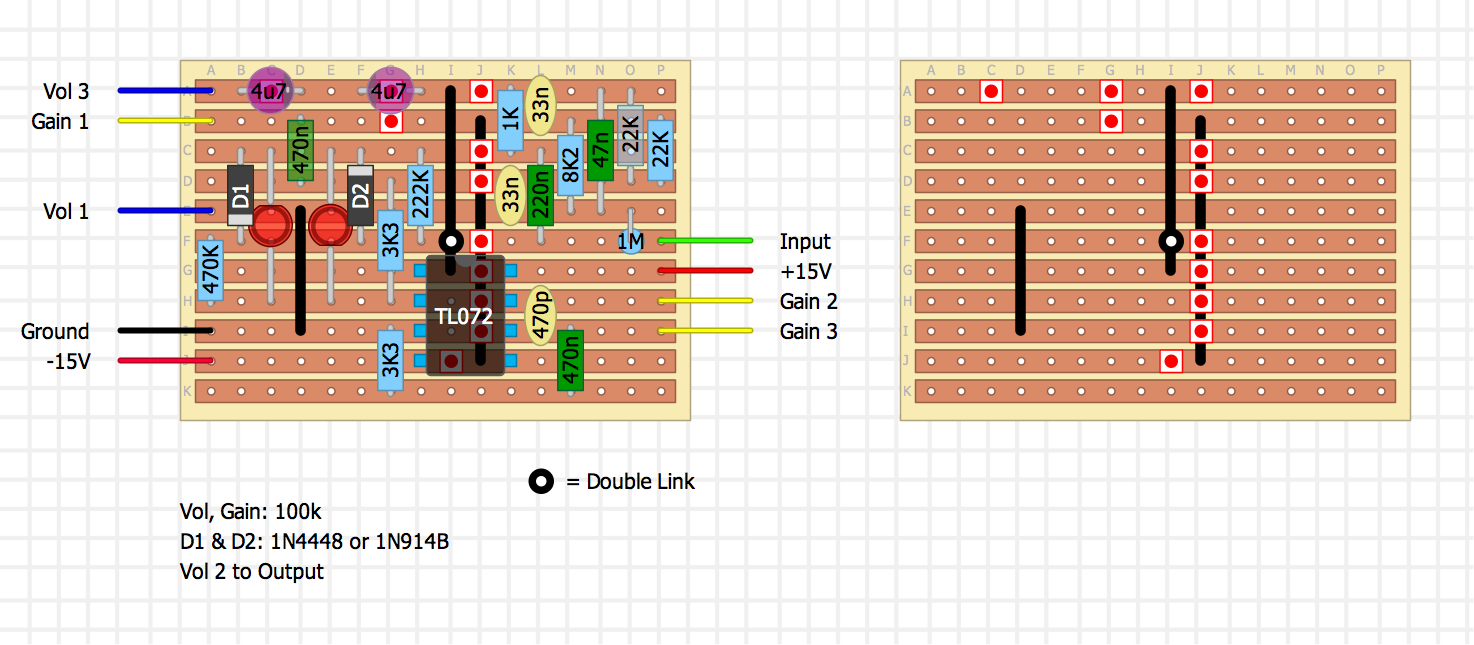
I committed the ultimate sin! A standing resistor! I know some people can't handle it, but it made the board easier, and I'm lazy.

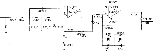
Give this a shot. No guarantee. You might want someone else's eyes on it before you build. I've been away from pedal building for a couple years so who knows if this will work, but I've gone over it a few times and it looks right. But I haven't built it, so consider it unverified. And it could definitely be done smaller... But I didn't worry about it too much, since this should fit in any box just fine. Only thing I wasn't sure of is the polarity of the 4.7u at the end of the circuit. If it needs to be reversed, I'm sure someone will let me know.

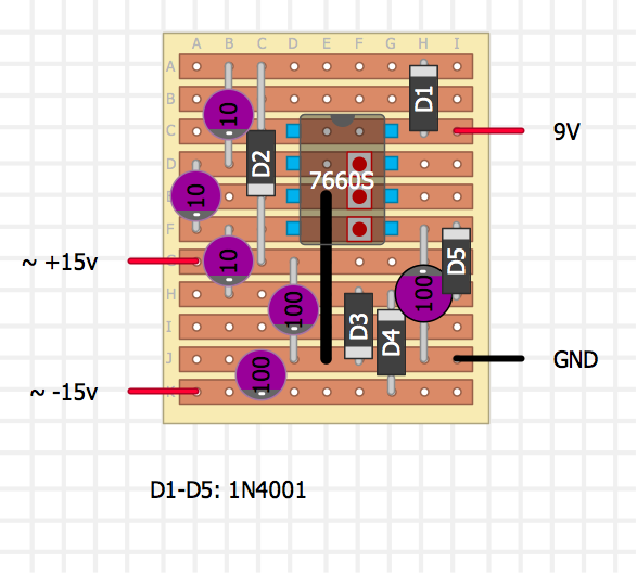
At first I tried to get everything on one board, but it was huge. So I would build 2 boards. The first takes your 9v power supply and converts it to ~ +15/-15v. It's one |v|ark posted a long time ago. But with the link removed between pins 1 and 8 I believe this should work with the easy to find 7660S chip.


Then just wire that up to the main board. The +15v and -15v outputs will just get wired over. No idea if the pots are linear or logarithmic.

[ SEE BELOW ]

Let me know if it works out. Also, I don't know how you plan to use this. But if you want it as a standalone pedal, you might want to add a tone control of some sort.
Reply | Threaded
Open this post in threaded view
|

Re: Overdrive circuit to vero Request

induction
The link farthest to the right should connect to the 2nd row instead of the first. To fix it, you can reverse rows A and B for columns A through J.

Other than that it looks good. There's no power filtering in the schematic, but it looks like the output of the charge pump is filtered.

Pin 1 of the TL072 should be at ground, so the output cap should really be nonpolar. I don't know how hard it is to find nonpolars in that value, but you can always just add a reversed 4u7 in series between the one that's there now and Volume 3.
Reply | Threaded
Open this post in threaded view
|

Re: Overdrive circuit to vero Request

jaredcohen
Oops! Thanks induction. I swapped those rows. But before I post the new layout, when you say to add another 4u7 with reversed polarity, you just mean like this, right? Doesn't that create only 2.35uf capacitance?

Reply | Threaded
Open this post in threaded view
|

Re: Overdrive circuit to vero Request

induction
That looks right.

 
jaredcohen wrote
Doesn't that create only 2.35uf capacitance?
With most caps, putting them in series reduces the total capacitance: C = C1*C2/(C1 + C2).
But the thing about electrolytics is they act like caps (they pass AC current and block DC) when correctly polarized, and act like jumpers (they pass AC and DC) when reverse polarized. So if you put them back-to-back with opposite polarity, you get something that acts like a cap in both polarities. On positive swings, one cap essentially disappears, and the other engages. On negative swings, they reverse. Since only one cap is active at a time, the pair behave like a single cap. In fact, non-polar electrolytics are made by combining polar caps just like this and putting them in a single package.

The problem with reverse-biasing a cap is that passing DC current harms the cap. Reverse-biasing with DC will kill the cap pretty quickly. Using polar caps for non-biased signal applications means it's only reverse-biased for short periods of time, so it will die slower. The series arrangement ensures that no DC passes through either cap, since each cap blocks DC in one direction.
Reply | Threaded
Open this post in threaded view
|

Re: Overdrive circuit to vero Request

jaredcohen
Ah, very cool. Thanks. I didn't know that. Electrolytic caps have always confused me.

Here's the layout if the OP wants to give it a shot. If you're looking for a place to connect the Ground from the voltage doubler board, you can use the far right hole on the row right above Input on the main board. That row is also ground.

Reply | Threaded
Open this post in threaded view
|

Re: Overdrive circuit to vero Request

matthew1234
Thank you everyone for your help! I really appreciate it!