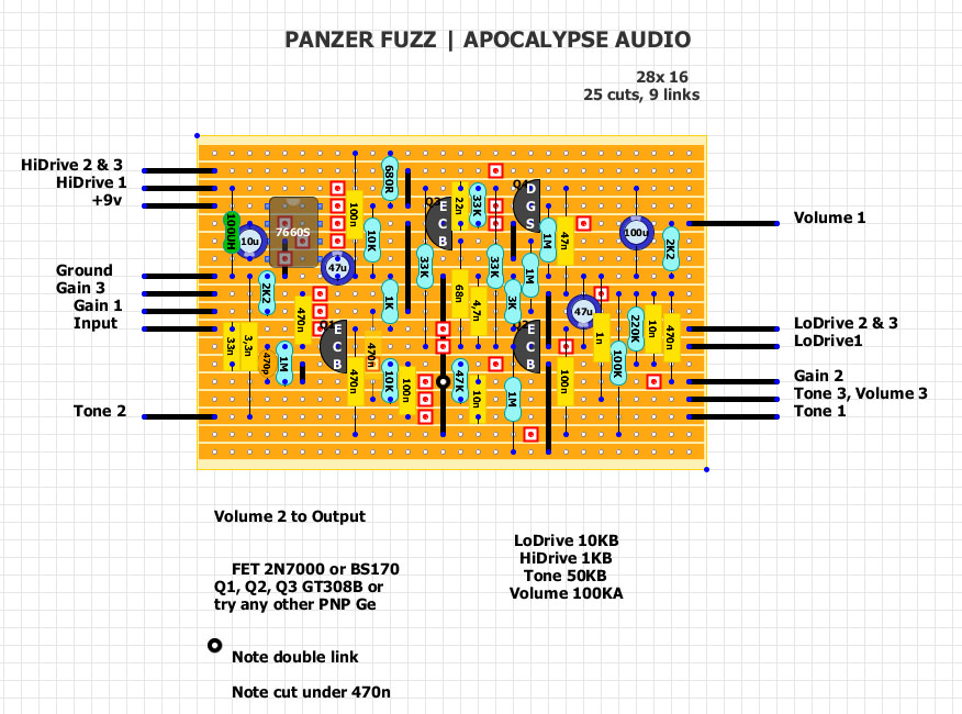
PANZER FUZZ APOCALYPSE AUDIO | GE + MOSFET FUZZTORTION | VERO INSIDE
|
This post was updated on .
Here we go again! This time seems a great project from Apocalypse Audio.
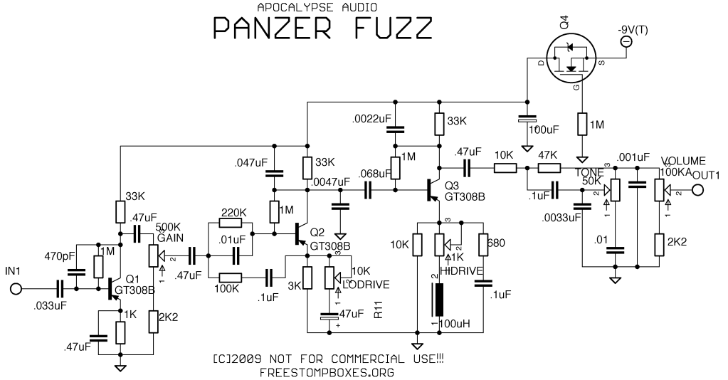
So i am very glad to Neil and others who can help on review this one. Schematic added. Only Mod: 9V inverter.  Exerpt from the site: my latest creation is an uber-high gain fuzz-tortion designed around the soviet GT308B germanium transistor. since this seems like one of the more common russian germanium transistors that people buy, i thought it would be a good candidate to include in my next project. the 308B has a gain that usually hovers around 75 in most specimens that i have seen, except for some batches marked with red dots that have a gain of around 20 points less on the Hfe reading. as with most other soviet Ge's, their leakage is pretty much nil, this allows for excellent stablilty, easy biasing without trimpots, and no need to do tedious gain/leakage checks. i thought the 308 would be the perfect candidate to design a high gain fuzz around because of it's relatively high gain compared to other russian Ge's, and i haven't done anything along those lines since the Toecutter, which although it is doomy as hell, it is in itself not all that terribly high gain anyway. the controls of this guy are as follows- gain, lo drive, hi drive, tone, and volume. the lo drive control is basically a full range gain control for the 2nd stage, and the hi drive control is i gain control for the 3rd stage that is concentrated only on the high frequencies. with all of the gain and drive controls turned up, you get an all out doomy grind with plenty of bite for on the top end. rolling back the gain control gives you a great crunch tone that i would describe as medium-high gain. the tone control is a heavily modified version of one that i saw on the AMZ site. i added 2 more caps, and adjusted all of the values for a nice even sweep. turning it all the way up also brings in a little bit of low end as well, so you get what sounds like a little dip in the midrange, too- adding to the metal tone of circuit. don't get me wrong though- this isn't one of those ultra-scooped metal zone P.O.S.'s. this thing has a ton of low end and has been tuned to have a bump in the high mids as well in order to cut through the mix and add some nice grind to the tone. 
|
Re: PANZER FUZZ APOCALYPSE AUDIO | GE + MOSFET FUZZTORTION | VERO INSIDE
|
great job man!
i've found just one mistake really easy to fix! the 47nf just after the first 33k should go to the collector of q2. you've made a link for that, but you've put 47nf one hole down. (and i didn't check the 9v inverter part) |
|
Thank you a lot for the rapid response ξεναγος.
Now 47nf is connected to Q2 Collector, vero updated. |
Re: PANZER FUZZ APOCALYPSE AUDIO | GE + MOSFET FUZZTORTION | VERO INSIDE
|
In reply to this post by boratto
thanks boratto!
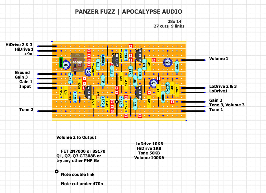
just one more think man.there is an easy way to make the board smaller if you're interested.(28x14) make a cut just in the left hole of q3 base.then take 680r from emitter down.(there is space for that), and then move 100nf so it will be connected from 680r to ground. that's -1 row and -2 is near q2. move the cut near base one hole left.take the link from right to the left side of transistor, from where the cut was, move 1m one hole up.(the link one hole up too).make one cut to prevent groundind to the left and move the other cut to the right next to 100nf. smaller is better in some cases! cheers savvas |
|
Savvas,
thank you again! Take a look, i think this is the way you think. 
|
Re: PANZER FUZZ APOCALYPSE AUDIO | GE + MOSFET FUZZTORTION | VERO INSIDE
|
yes mate! that was what i was thinking!
i have the same frustrating row in my layout for mobius trip looper but i couldn't avoid it...so when my eyes fall in this "boardspace-things" i allways try to "solve" them!! great job again! |
Re: PANZER FUZZ APOCALYPSE AUDIO | GE + MOSFET FUZZTORTION | VERO INSIDE
|
In reply to this post by boratto
sorry Borrato the count on top to bottom rows are wrong here.The Smaller version is 28x16 and the layout at top is 28x18.I'm building the smaller version now,wanted to let ya know about the size difference.Thank you very much for posting this layout.i cant wait to finish this and hear what it sounds like.
|
«
Return to Unverified Layouts
|
1 view|%1 views
| Free forum by Nabble | Edit this page |

