Parallel Channels Wiring? Stereo unit.

classic Classic list List threaded Threaded
5 messages Options
Reply | Threaded
Open this post in threaded view
|

Parallel Channels Wiring? Stereo unit.

sean2damax
This post was updated on .
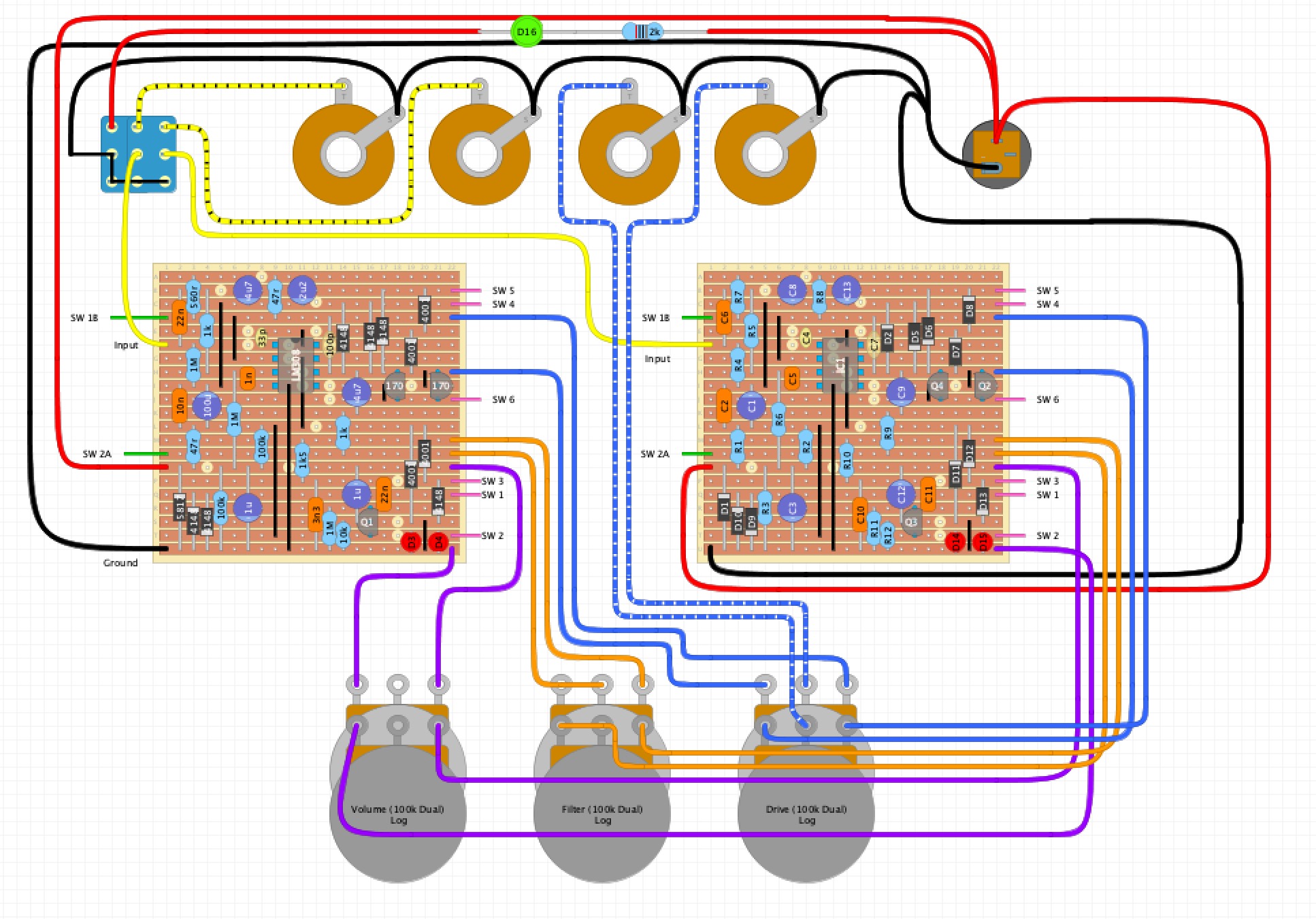
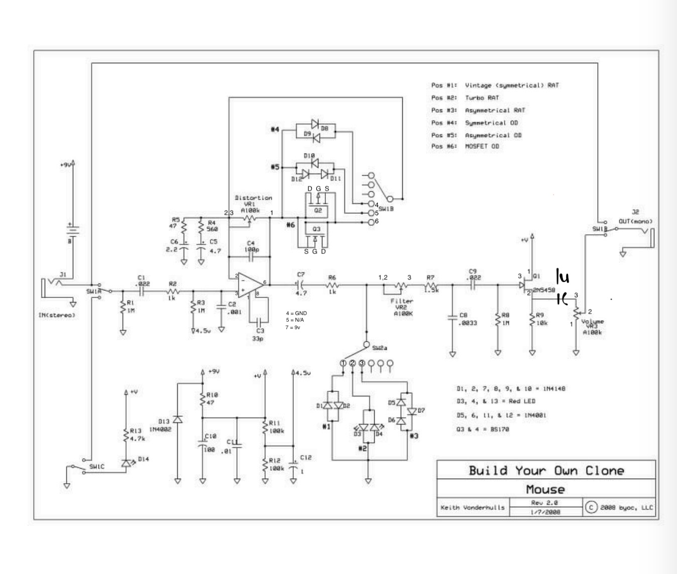
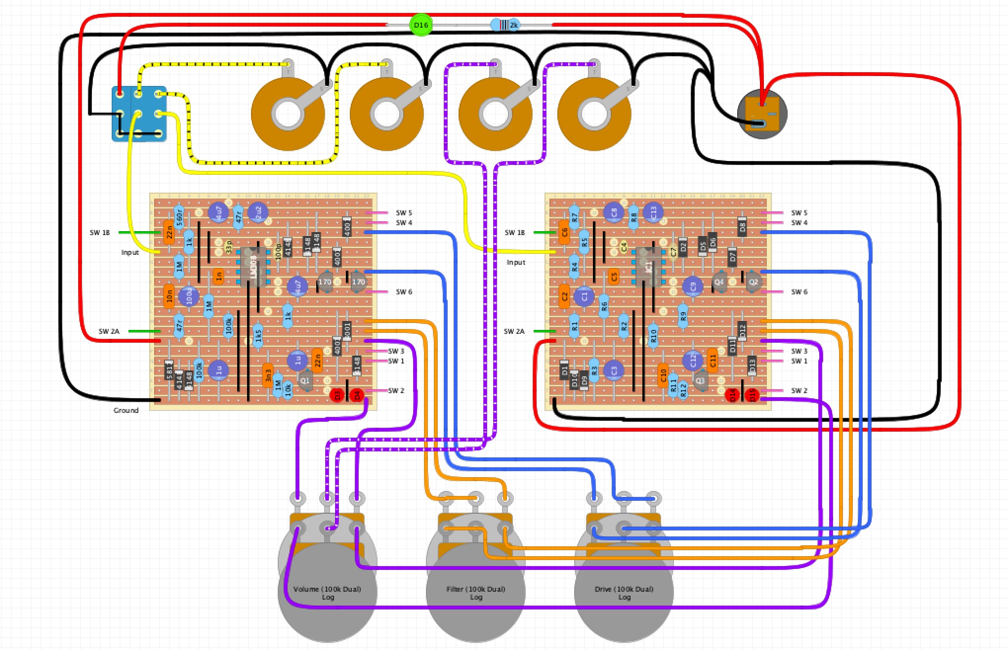
I was hoping I could whing this one but i'm running into a wall here. I'm putting together a two channel Rat with different clipping modes for a buddy to use in his studio. I made the layout from BYOC's Mouse v2 schematic.

The layout works properly when it's hooked up like a normal mono guitar pedal, but something i'm doing when I box this up is making it not work.

- I'm getting no signal passing, and oscillation based on the position of the pots.
- I wired the 3pdt to send each input to ground.
- I'm getting the proper readings on the LM308 pins (The chips are from SB and are confirmed to work)
- Pot values need to be linked for this to work as intended, so i'm using dual gang A100k pots

I suspect my grounding scheme is to blame, but i haven't been able to fix it so what do I know haha.

Edit: This doesn't need true bypass. I just want to be able to kill the signal so it doesn't pop when you're plugging it in or removing cables.

LayoutBYOC Schematic
Reply | Threaded
Open this post in threaded view
|

Re: Parallel Channels Wiring? Stereo unit.

Travis
Administrator
There are mistakes in the pot wiring and I think you should rethink the input/output and bypass a bit. Really it’s probably easier and more practical to wire this up like two pedals in one box. If you want to split the signal into both inputs at once it’s best to do that with an active buffer. Likewise if you want to sum the outputs it’s best to use a buffered mixer.

As you have it now the pedal will mute everything in bypass mode. With that said it is really redundant to use a 3PDT for that because you could simply switch the power with an SPST and have the same functionality
Reply | Threaded
Open this post in threaded view
|

Re: Parallel Channels Wiring? Stereo unit.

sean2damax
Wow. Can you tell I made that while I was watching OSU/Clemson last night? whoops. That's not how the pots are wired haha. Vol 2 should go to output and Drive 2,3 are linked. Attached a fixed diagram.

Point well taken on the spst, that would have been more efficient. I'm already using a toggle, so I might go ahead and make that change.

This isn't intended to be used as a guitar effect. It'll be seeing separate L/R channels of audio in a studio, so having "two pedals in one box" is definitely the intent here.

Any splitting or summing will be done outside of this box (again, this is going to a studio), so buffered splits or sums wouldn't be applicable here right?

I do need the pots to be linked so that they can be reliably affecting each channel the same way.

Sorry for all the questions, just trying to learn so I don't have to lean on the forum next time. Much appreciated.


Reply | Threaded
Open this post in threaded view
|

Re: Parallel Channels Wiring? Stereo unit.

Travis
Administrator
Ah that makes sense. If you post voltages and pics that might help narrow it down faster
Reply | Threaded
Open this post in threaded view
|

Re: Parallel Channels Wiring? Stereo unit.

sean2damax
Ok, so I had been testing this one side at a time. I finally ran it though my DAW and routed things to split my guitar and then sum it back so I could hear what was happening on each side simultaneously. This works perfectly when both sides are plugged in.

Looking at the schematic, I assume the bled signal to ground was coming back into the second circuit through the hard clipping diodes? Either way, the unit is working as long as everything is plugged in, which it needs to be anyway to be used as intended.