So, I got a request for a pedalboard interface. There were many specifications to be met, buffers, amp's loop routing, stereo output with summing possibilities... I finally designed it and now I am at the last stages of building it. That means it is not tested yet but is is a slow afternoon so I thought I'd share what I have.
Warning, this isn't gonna make much sense until you have the whole picture. :)
Also warning, I left all the pictures uncompressed, some are pretty huge!
****UPDATED 8/12***** Built, tested and verified :D
Well, that had some issues at the first testing session, I went back to the drawing board and now everything works as it should. All documentation beneath is correct and tested.
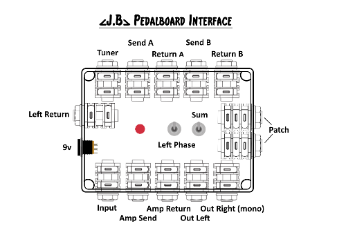
Here goes the box layout as seen from above. Hammond 1550M used, a bit bigger than the 1590BB cause I wasn't sure everything was gonna fit in. After finishing I think the BB could fit everything with some precision planning and drilling. I moved the led and the switches around a bit in my build, there is enough room to install them wherever you please. The two "patch" jacks are not listed furthermore in the documents, they are just linked TRS jacks to be used for any patching needs (e.g. an expression pedal)

Then the Board use for all the buffering.

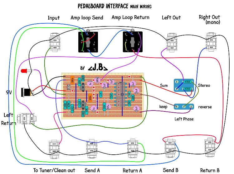
And here is a "master wiring" diagram as shown while looking in the box. Notice the two jacks used for the amp's loop, they are stereo jacks with 2 x SPDT switches. Their application is explained in this post
http://guitar-fx-layouts.42897.x6.nabble.com/Moving-effect-from-chain-to-amp-s-loop-td47481.html
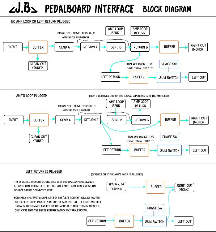
Finally, I tried to draw up some pictures to explain how the whole thing is supposed to work.

I will post all the pics on full size beneath, as well as some pictures of my build.
I may have forgotten to explain some things, feel free to ask me if you need any info!