Please Mark my homework.


|
Hi Guys so over the weekend i built the EQD Chrysalis. I have to say it's the best overdrive I have heard so far and when I plugged it into my old Fender Champ Clone, I just went ARRRRRRRR, that's the sound I have been looking for.
I have ordered the parts to build another one this time I am hoping to tweek. As I am quite new to the hobby I was hoping for some help. I have found this Schematic from the link on here... 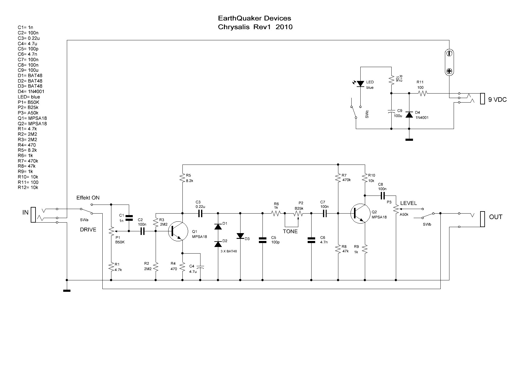 From what I have learnt so far: The circuit looks like an electra drive going into an LPB 1 style boost stage with a tone shaping in the middle. So looking at the schematic I think C1 is a decoupling cap and is there to remove any DC from the guitar signal. Is this right? If C1 is a decoupling cap then I do not know the function of C2. Guessing I would say it is some sort of tone shaping and would shave off some bass. P1 is the drive pot but I don’t understand how drive can be set here. I thought the guitar signal would be too weak to really have any effect but obviously I am wrong. Any help explaining how it works would be appreciated. Again I am at a loss as to how R1 affects the circuit, help or pointing me in the direction of a good resource to help would be appreciated. I believe R2, R3, form a voltage divider and that is Vout= 4.5. This is the bias for the first Transistor?? And goes to the base. I get the Transistor I think it amplifies the signal?? R4 is to bias the Transistor at the stage if you decrease the value it will add more gain and decrease less gain?? This goes to the collector. R5 sort of does the same job and the value changes will have the same effect but joins the emitter to ground. I have no clue what C4 does. I may be thinking feedback but i don’t know.. Please can you help. C3 is again a coupling cap and is there to remove any dc? The diodes clip the signal and placing different diodes will clip the signal in different ways. Like the switch in my Rat Clone. Asymmetric, Symmetric, and so on. The next stage is the tone control. I am not sure of the function of R6. The capacitors C5, C6 affect the cut of the tone pot. Changing the cap values will alter the tone like upping the values will roll off more highs. Does anybody have a suggestion for a good mid boost value in this circuit??? C7 is a coupling cap and is there to remove any DC picked up from the diodes and tone control. But does this also work by shaving off some highs. I am not sure why R5 is connected to R7 my guess would be they share the 9v supply as R7 forms a voltage divider with R8 form a voltage divider to Bias the second transistor. The voltage works out at Vout = 0.818. I am thinking that the second transistor turns on a 4.5 volts as it's the same MPSA 18 as the first Tranny, so the remaining voltage is coming from the first transistor? R10 and R9 do the same job as R4 and R5.. The Last cap C8 is there again to remove DC and slightly shape the overall tone. The Last pot is just volume control. Thanks guys in advance for the help |
|
|
This post was updated on .
A "drive/dirt/gain/fuzz/distortion" control in a dirt pedal can operate in different ways, sometimes by altering the actual gain available via feedback within the circuit (e.g. fuzz face, many opamp distortions), sometimes they work by adjusting the level of signal passed between two stages (e.g. big muff), and sometimes both at once (marshall bluesbreaker and similar gain pots). In this case, the amount of dirt is controlled by the guitar input level into the circuit: It is effectively a second volume pot between your guitar pick-ups and the circuit input, and if you roll it up to maximum, and diddle with the guitar volume pot, you will probably get a similar effect to the drive pot. C2 is the actual input cap to the circuit, although C1 and C2 act in series as "DC-blockers"/coupling caps between guitar input and Q1's base. C1 is a very low value compared to C2 - It is only there to allow the very highest frequencies of the guitar through even when the dirt pot is turned very low, helping preserve a bit of sparkle at low gain. C2 will not shave off much bass at maximum gain due to it's large size (most frequencies preserved down to almost sub-audible), although the bass frequencies will be reduced as the dirt control is wound down. R1 sets the minimum gain level: The pot is exactly like a volume pot (input goes to lug 3, output from lug 2, and lug 1 to ground), except it cannot be shut off completely due to R1: You cannot ground the input of the circuit completely, there will always be roughly 5% of the signal allowed through. R2/3 do help set the bias of the transistor, along with R4 and R5. The collector might (need to?) be near 4.5v operating voltage, but not necessarily so. That 4.5v is often quoted as the ideal for a fuzzface Q2, but this is very dubious advice, and the "ideal" collector/drain voltages for 9v dirt devices vary considerably from circuit to circuit and between different spec devices in the same circuit. I think the idea is that biasing to 4.5v (or slightly above) gives the greatest "headroom" for input voltage swing using a 9v supply in order to minimise distortion, but this is not that relevant for dirt boxes. Yes: Increasing R5 or decreasing R4 will increase the circuits gain, but will also move the bias point (or collector voltage) around.... see above. C4 does have an effect on feedback via "emitter degeneration". Remember that if we lower R4 value, we got more gain? The more current that can flow to ground through the emitter, the more boost we give to signal from base-to-collector. Because it is a resistor it allows both AC and DC to pass from collector, though emitter to ground. Why not just ground the emitter and not use a resistor at all here, since no resistance = maximum gain? Well, if the emitter is grounded we get more gain but lose stability in the circuit and reduce the tolerance of the circuit for variety within the specs of the actual transistors we can use. By lowering to 470ohm (very low) we got lots of gain, and adding C4 allows that 470ohm resistance to be bypassed by AC voltage, effectively boosting the gain to maximum AND the 470r gives the circuit stability and we can use pretty much any part number NPN BJT from a wide range of different gain specs and it will sound pretty similar. Yes. Without the diodes, we would probably only need C3 OR C7, not both. However, capacitors block DC, but diodes do not, so the voltage on the collector of Q1 and the base of Q2 would see a DC path to ground through D1/2/3 if C3/7 were not in place. Yes for the diodes, yes for the caps. R6 sets the maximum treble setting of the tone control. As P2 control is turned up, the resistance the signal has to pass through before reaching C6 is decreased and the amount of treble that passes is increased: At maximum treble, there is still a small (1k) resistance in this path. Removing the 1k will make the brightest sound a tiny bit brighter, but increasing it's value will make the make treble setting sound darker. Mid boosts are tricky-ish (compared to boosting bass or treble) - It is usually easier to boost the entire signal and the shave off the treble and bass for a mid boost. The simplest active midboost would be something like this - 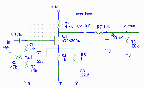 ..... but I don't know whether you would want to build it as a separate effect to go before the circuit, or try it out on the breadboard between the clipping diodes and the tone control. C7 does isolate DC at the base from ground via the diodes, but this capacitor is in SERIES with the "signal flow" and so will act as HIGH pass filter. It allows ALL frequencies to pass at the top end, but has a HPF cut-off frequency that is inversely proportional to the capacitance value: Larger capacitance = lower cut-off. In this case 100n allows "high" frequencies through all the way down to quite bass-y regions of the spectrum (although in reality, some bass will have already been lost in the clipping section). By contrast, capacitors that link the signal to ground or virtual ground will act as LOW pass filters on the signal (e.g. C6): They allow all low frequencies to pass, up to an LP cut-off frequency set by the capacitance (and resistance in series, i.e. the 25k pot) and will "bleed off" these frequencies higher than the cut-off to ground. Yes - R5 is only "connected to R7" in the sense that they are both connected to +9v. You could equally state that all components R1,2,4,8,9 and C4/5/6 are all "connected together" because they meet at ground. No audio signal can "pass through" the 9v or ground connection from one component to another unless the gain is so high you start to get self-oscillation through the rails. ? Yes, yes, yes, and no problem. |
«
Return to Open Chat
|
1 view|%1 views
| Free forum by Nabble | Edit this page |