Loading... |
Reply to author |
Edit post |
Move post |
Delete this post |
Delete this post and replies |
Change post date |
Print post |
Permalink |
Raw mail |
![]() ![]() ![]() ![]() ![]() ![]() ![]() |
809 posts
|
Had a request to build a delay unit with two different delay times that are foot switchable.
My immediate thought was a 4pdt stomp switch that would switch between two different time pots and an led to indicate which pot was active. Would this create any weird popping sounds or create other problems? |
Loading... |
Reply to author |
Edit post |
Move post |
Delete this post |
Delete this post and replies |
Change post date |
Print post |
Permalink |
Raw mail |
![]() ![]() ![]() ![]() ![]() ![]() ![]() |
Administrator
1993 posts
|
What delay circuit are you using?
If it's a PT2399 circuit you can switch the pots using just a SPDT. DPDT if you want LED indication. With a PT2399, the delay time pot is a variable resistor to ground (only two lugs on the pot are needed). You can keep lug 1 of each pot permanently wired to ground, and then switch between which pot has lug 2 connected to the circuit |
Loading... |
Reply to author |
Edit post |
Move post |
Delete this post |
Delete this post and replies |
Change post date |
Print post |
Permalink |
Raw mail |
![]() ![]() ![]() ![]() ![]() ![]() ![]() |
954 posts
|
In reply to this post by Sensei Tim
If it's a PT2399 delay, the delay time is controlled by a pot wired as a variable resistor, which means it only has two connections, so it can be swapped with a single pole, and you can use a DPDT (one pole to swap pots, the other for the led. Obviously, you can also use a 3PDT if you prefer.
As for popping, the delay pot is not in the audio path so I would guess that it won't pop, but I'm not making any promises. Edit: Travis is a ninja, and his idea is better than mine. |
Loading... |
Reply to author |
Edit post |
Move post |
Delete this post |
Delete this post and replies |
Change post date |
Print post |
Permalink |
Raw mail |
![]() ![]() ![]() ![]() ![]() ![]() ![]() |
809 posts
|
It probably will be a pt2399 delay. Not sure which one yet tho. Just wanted to make sure that I wouldn't run into any unexpected problems.
Cheers! On Saturday, September 3, 2016, induction [via Guitar FX Layouts] <[hidden email]> wrote: If it's a PT2399 delay, the delay time is controlled by a pot wired as a variable resistor, which means it only has two connections, so it can be swapped with a single pole, and you can use a DPDT (one pole to swap pots, the other for the led. Obviously, you can also use a 3PDT if you prefer. -- Sent from Gmail Mobile |
Loading... |
Reply to author |
Edit post |
Move post |
Delete this post |
Delete this post and replies |
Change post date |
Print post |
Permalink |
Raw mail |
![]() ![]() ![]() ![]() ![]() ![]() ![]() |
Administrator
1993 posts
|
In reply to this post by induction
Well if my idea is better than yours that would certainly be a first lol What do you think of this idea though induction? I think you may be able to switch both the delay pot and LED with a single SPDT. 
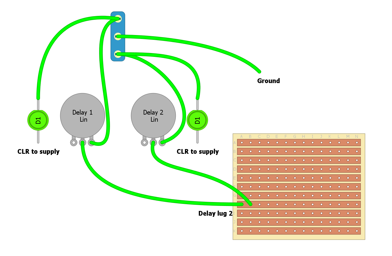
Instead of having each pot's lug 1 wired permanently to ground, instead have each pot's lug 2 wired permanently to the board. Then connect ground to the common lug on the SPDT (lug 2) Wire each pot's lug 1 to the outer lugs on the switch respectively This way, the switch is choosing which delay pot is connected to ground, as opposed to which is connected to the circuit. THEN, you can share a connection on the outer switch lugs with each pot lug 1 and it's corresponding LED cathode This is probably not a good explanation at all. I am not very good with words sometimes (most of the time). But I think this will work perfectly with just an SPDT |
Loading... |
Reply to author |
Edit post |
Move post |
Delete this post |
Delete this post and replies |
Change post date |
Print post |
Permalink |
Raw mail |
![]() ![]() ![]() ![]() ![]() ![]() ![]() |
Administrator
1993 posts
|
Here's a quick diagram to clarify
![]() |
Loading... |
Reply to author |
Edit post |
Move post |
Delete this post |
Delete this post and replies |
Change post date |
Print post |
Permalink |
Raw mail |
![]() ![]() ![]() ![]() ![]() ![]() ![]() |
954 posts
|
The switching logic seems sound enough.
In practice, the led switching might cause some instability in the voltage at the ground node, which might have an audible effect on the delay time. Or it might not, you'd have to test it to be certain. |
Loading... |
Reply to author |
Edit post |
Move post |
Delete this post |
Delete this post and replies |
Change post date |
Print post |
Permalink |
Raw mail |
![]() ![]() ![]() ![]() ![]() ![]() ![]() |
Administrator
1993 posts
|
I just checked an existing build with my multimeter
The ground node on the switch (for the LED) stays at a steady 0V while the LED is on, off, or being toggled I wouldn't expect any issues, but can't rule it out either |
Free forum by Nabble | Edit this page |