Another bump from the dead :)
Don't know if anyone else is still interested in this, but I thought it would be worth sharing my experiences over the past couple of weeks with this circuit, in case they can help anyone.
This is my first time posting on the forum - I've used the site for a couple of years, made a few different pedals but never ventured into the forum before. A couple of months ago I became interested in making a JC120 preamp for myself, and I had a look on the main site for a layout. I didn't find anything there, so I went looking for a schematic, without thinking to check here.
I found this forum thread:
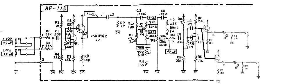
https://www.diyaudio.com/community/threads/clone-preamp-section-of-jc-120.326876/ . The first post there includes a service manual for a later version of the amp from the one Tim posted above.
Roland_JC-120,_JC-160_(79-4)_Jazz_Chorus_Service_Manual.pdf The schematic in this manual looks exactly like what was posted on page 1. So that seems to explain the difference in the schematics.
It may be worth noting that the voltage on this schematic is 27V, not 30V; but as others have noted, the circuit works with other voltages (I plan to run mine on 24V). Also worth noting that the 100k resistors on the output (R29, R32 and R33) seem to be for channel mixing to the power amp (since it's a stereo amp), and aren't necessarily related to the preamp. On the diyaudio forum post, there's a suggestion to remove them entirely.
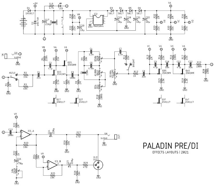
I tried to breadboard the 1st channel preamp from this schematic. Everything worked fine for me up to 3rd gain stage (Q4) - before this stage, the signal was very clean and bright, sounded good; after this stage, it was very easy to make the signal clip. I'm not sure what I did wrong to make this happen - it wasn't the jfets because the same thing happened when I switched them out (I got mine from retroamplis, so I'm fairly confident that they're ok). It could be that Q4 needs more careful biasing, but I didn't test that. I also included the 100k resistors channel mixing resistors, as I was wanting my preamp to have 2 outputs. I found that there was an obvious signal drop, and the signal lost a fair bit of brightness as well. I ended up removing Q4, and adding 2 copies of Q2 to the output (both suggestions from the diyaudio discussion) - this gave me a nice clean signal with 2 outputs. The schematic of my circuit looks like this:
.
It's clearly modified from the original schematic, but it retains the same character, and has the 2 outputs I need, so I was happy.
From that, I created a layout. This was my first layout, so I know it could be a lot better, but I'm running out of time to make it up for my purposes, so it's a quick and dirty job:
JC120_Preamp_layout_V2.pngFWIW, my 24V supply is coming from this:
https://www.robotshop.com/uk/dfrobot-dc-to-dc-step-up-voltage-regulator.html. I'll be putting 9V on the input from my pedalboard power supply.
I'm still in the process of making up this board, so I don't know if the layout will work, but I'll post an update here over the next couple of days once I get it completed. The circuit in the attached schematic definitely works, so I'm hopeful. EDIT: I have now completed the pedal, and it works - although there were a couple of errors on my layout. I have now uploaded an updated layout (v2), this works correctly.
It would be great if we could get a version of this layout that works for everyone and doesn't cause so many issues - hopefully what I've put here will be able to help make that happen :)