Problems with Keeley 4 Knob Compressor

classic Classic list List threaded Threaded
4 messages Options
Reply | Threaded
Open this post in threaded view
|

Problems with Keeley 4 Knob Compressor

Gingerbwas
Hi

I am fairly new to all this so apologies in advance if I make any obvious mistakes.

I am having trouble with the 
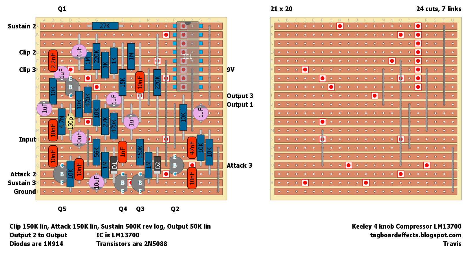
Keeley 4-Knob Compressor and I am unsure how to solve the problem(s).

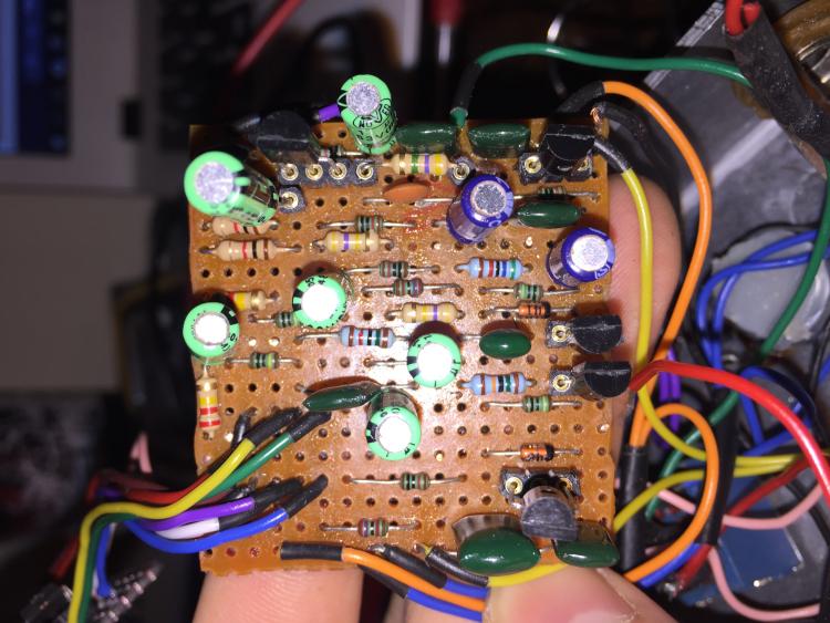
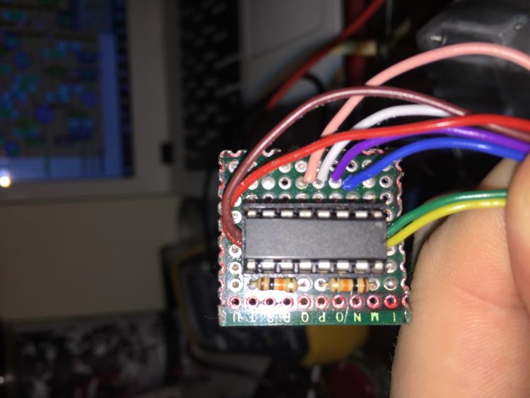
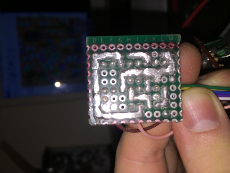
 I have gone through the board multiple times to check for mistakes, missing parts, unwanted solder bridges etc, and i cant see any, the offboard wiring that I am using is this one  here, the true bypass seems to work okay by itself the LED turns on and I get the guitar signal through, however when I connect the 9v wire from the board to the power jack (With all other wires being connected), the red light cuts off. when I tried to use a new battery the battery itself and the wires connecting it to the power jack got hot, although if I use an older battery (that works with other pedals) it does not get hot.

I have used an 
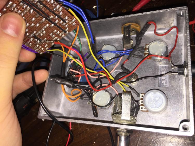
audio probe to try and find where the problem comes from but I don't really understand what the results indicate. The picture below shows the parts that get a signal from the probe in green, and the parts that don't have green marks means no signal through the probe.


when I connect my multimeter to the positive and negative on the battery I get about 0.04v

one of the parts that might be a problem is that I couldn't find a ca3080  so I used this instead.

sorry, the photos seem to be rotatated 90 deg counter clockwise, im not sure how to change that.


Any help will be greatly appreciated.

Liam


Reply | Threaded
Open this post in threaded view
|

Re: Problems with Keeley 4 Knob Compressor

Ciaran Haslett
Hi Liam and welcome.

How are you dealing with the double links in the layout? (Blue dots)

The purpose of these blue dots is to tell you that a link must also be soldered to this spot.  For example...

There's a link from the 9V row that goes to pin 7 of the 3080
Then there's another link from pin 7 to between the two cuts further down.

I don't see any of that in your build.

When the power supply get hot or suffers a significant voltage drop it usually indicates a short somewhere or a misplaced/mis-valued component so maybe have another close look at the board.

Also...maybe try to get in the habit of using component leg cut offs for the links and place them on the component side of the board rather than the solder side.  I usually place a few resistors, verify their placement, then cut off the legs and use those for my links.  It makes troubleshooting much easier when you don't have to constantly flip the board around.  Just my 2 cents.

So verify the above and let us know how you get on.

Good luck
Reply | Threaded
Open this post in threaded view
|

Re: Problems with Keeley 4 Knob Compressor

Gingerbwas
Hi, thank you for your help.

i went through everything that you suggested, after re wiring all the off board components and and rewiring the links with the blue dots and on the other side of the board and now the short has gone, the battery stops getting hot and the is on all the time.

however it still doesn't work and i cannot for the life of me find out why,
ive taken the following readings from the transistors and ic but i dont know enough to know what they mean, any help you can give will be greatly appreciated.

These reading were taken with the black prong of the multi-meter on ground and the red prong as the probe.
Q1

E - 4.34
B - 4.85
C - 4.30

Q2

E - 4.45
B - 5.05
C - 4.45

Q3

E - 0
B - 0.02
C - 7.75 (although when i took the reading it would keep fluctuating between 7 and 1

Q4

E - 0
B - 0.06
C - 7.45 (Same fluctuation)

Q5

E - 7.44 (Same fluctuation)
B - 7.55 (Same Fluctuation)
C - 8.44

IC

1 - 0
2 - 1.18
3 - 1.18
4 - 0
5 - 1.17
6 - 3.44
7 - 8.44
8 - 0.01

Thank you in advance for any help.

Liam
Reply | Threaded
Open this post in threaded view
|

Re: Problems with Keeley 4 Knob Compressor

Travis
Administrator
There are multiple bad looking solder joints there. The battery heating up and all that indicates a short somewhere on the main board or daughterboard

Check continuity and/or resistance from 9V to ground on the main board and daughterboard to check for a short

If you want to start over from scratch, here is my verified layout for the Keeley with an onboard LM13700