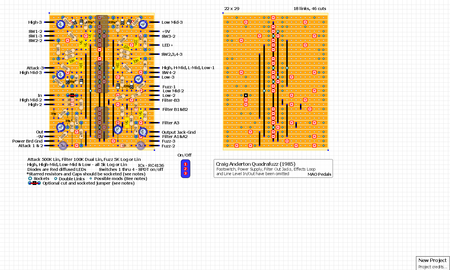
Here is my 1590BB version of Craig Anderton's Quadrafuzz.
I had built the complete original back in 1997. I don't remember why, but I wasn't crazy about it then.
For some reason I decided to make a vero layout...and I'm glad I did!
This is a really unique sounding circuit. Much better than I remembered and much better sounding than the youtube videos I found on the newer version.
I have omitted the electronic footswitch, filter output jacks, effects loop, the line level in/out and the +/- power supply from the layout. (I seem to recall Mark Hammer had posted a similar stripped down schematic back in the day)
I have socketed a few components based on a couple of suggestions from Mark Hammer.
1. Mark had suggested increasing the gain of the distortion circuits for each of the higher frequency bands so they clip at the same level (or something like that

). The 100k resistors and 220p/470p caps have been socketed for the Low-Mid, High-Mid and High band distortion circuits (They are near the LEDs). The lowest frequency band components are not socketed and remain as is. If you do increase the 100k feedback resistors, then you'll need to decrease the 220p/470p feedback caps if you want to keep the same frequency "corner". I went with 150k/150pf for Low-Mid, 220k/100pf for the High-Mid and 270k/180pf for the High band. That increased the gain for each band as follows: Low stayed at 30x, Low-mid is now 45x, high-mid is 66x and High is 81x. The lower cap values kept all 4 frequency rolloffs about the same as Craig had originally designed.
2. Mark also suggested possibly increasing the gain just before the tone control, that's the socketed 2k2 resistor at the bottom right of the board. I tried 10k, huge bump in volume. Right now I have the 2k2 back in place.
3. Since I removed the electronic footswitch and went with the standard 3PDT true bypass, it's possible there will be a "pop" when the stomp switch is engaged. So I put a socketed jumper on the board at the input so I can swap it for a 10n cap if needed. I also left room for a 1meg pull-down resistor. And if it is needed, it will go up diagonally at the input across the 2 empty blue pads, the top end of the added pull-down resistor will fit nicely under the socketed High-Mid feedback resistor and the bottom will go to the blue pad directly after the input. I also socketed the input's 10pf cap and 220k resistor which are towards the bottom left of the board. If I go with the 10n and 1meg pulldown, and if there is no RF interference I may not need the 10p and 220k and they can then be removed. I didn't notice any pops (or RF interference) in my test jig with the original setup, we'll see once I have it boxed up. (I believe Mark Hammer had also suggested this as well, or something similar)
4. I socketed the "Low level Out" 10k resistor in case I ever want a "Line Level Out" at some point. I couldn't see the need for now, so rather than having another switch I just socketed the resistor. It is the 10k resistor at the bottom left of the board. The "Line Out" resistor was 68k in the original schematic.
5. Others sockets worth considering are for the "Resonance Peak" resistors. Those are the 4k7 and 10k resistors at pin 2 of the "Q" switches (SW2-2, SW3-2 and SW4-2). I didn't socket those myself, but it might be worth doing so. Or you could even use On-Off-On SPDT switches for the Q switches and hang a different value resistor from lug 1, then run a wire from the other end of that resistor to the appropriate spot on the board, which would be the unused blue pads next to the socketed "Q" resistors. This would give you the original 2 settings plus a 3rd setting of your choice for each of the Q switches. Maybe something in between the lo and hi stock settings would make it worthwhile.
I used 4.7uf and 4n7 for the 5uf and 5nf caps. I also used matched sets for the 5nf, 10nf, 22nf and 33nf filter caps.
With Mark Hammer's suggestions, the Quadrafuzz sounds really good to me now. The thing I'm not crazy about though is the tone control, it only seems useful on the last 1/4 turn.
Anyway, here is the layout (verified by me)
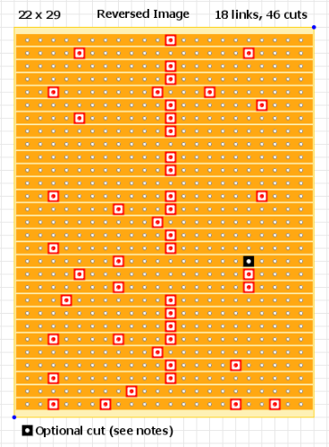
Here is a reversed image for the cuts
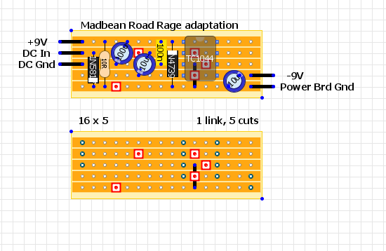
Here is the daughterboard I used to power it, Madbean's Road Rage, overkill but I had the room.
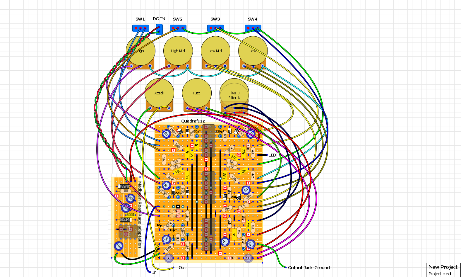
And here is how I wired it up
And here are a couple pictures of the boards and pedal guts
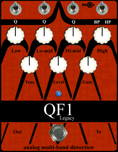
And here is my Iron Ether QF2 inspired faceplate, (black knobs look better)
1978 Gibson Les Paul Standard, Cherry Sunburst

