Quick NPN to PNP conversion question.
Quick NPN to PNP conversion question.
|
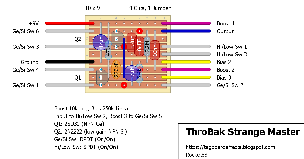
I would like to use PNP transistors in this "strange master" circuit, but in doing research on how to do that, I'm getting a little mixed up.
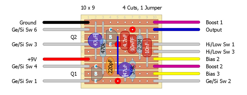
Here is the original:  do I just switch the +9V and ground on the board, and flip the electrolytics? I don't need to flip the transistors though, right? is this correct?  Thanks you for any help! |
|
Administrator
|
Hey man. All you need to do when switching from NPN to PNP is flip the caps and the positive and ground. So +9V goes to where ground would go, and ground would go to where +9V would go.
|
Re: Quick NPN to PNP conversion question.
|
This post was updated on .
Thanks for the response!
And forgive my ignorance, but by converting this to PNP makes this a "positive ground" circuit, correct? So, I can use a battery or a separate positive center power supply and my daisy chained negative center power supply cannot be used - right? EDIT: I found the following info that cleared up a lot of my polarity questions here: "Negative and positive ground pedals can be used together in any combination. What you can't do is use one single-polarity power supply for positive and negative ground pedals. The positive ground pedals connect the positive side of any power supply that gets connected to them to signal ground internally. The negative ground pedals internally connect the negative side of any power supply that gets connected to them to signal ground. If you have a positive ground pedal and a negative ground pedal with a signal cable between them on a single power supply, then both the negative and positive sides of the power supply are connected to signal ground, and the power supply is shorted. The answer is to use two different power supplies. One power supply can run as many negative ground pedals as you like, the other power supply can run all of the positive ground pedals. You just can't have the ground on a single power supply connected to both positive and negative sides." |
|
Administrator
|
Correct it will be positive ground. You can use a standard DC jack, you just can’t daisy chain it with NPN (negative ground) effects unless you put in a +9V to -9V converter in the same enclosure or you’re power supply has a -9V output.
|
Re: Quick NPN to PNP conversion question.
|
Perfect! Thanks for the help.
One last thing, the "bias" pot goes silent when turned fully clockwise. I was experimenting with a 10k resistor from lug 3 to ground, but that's not working...any ideas? Thanks again! |
|
I haven't built this, but biasing a transistor usually requires some finesse. This is why the bias is often set internally with a trimpot or fixed resistor.
When I add an external bias control in other circuits, I use a pot wired as a variable resistor to dial in the full range of acceptable sounds by ear. Then I measure the maximum and minimum resistances that corresponded to that range. Next I add a fixed resistor* to set the minimum resistance and select the value for the external bias pot so that it gives me the full resistance range when placed in series with the fixed resistor. I also measure the maximum and minimum acceptable bias voltage and record it for later troubleshooting. In general, I've found that the resistors and pots have to be selected by hand for each transistor. Since you are selecting between two transistors here, that can complicate things even further, since the ideal bias range might be different for both of them. I haven't seen the schematic for this, but without the fixed resistor to set the limit, silence at one end of the pot range is probably expected behavior. Depending on how well the pot value matches the acceptable bias range, the sound at the other end of the pot range may not be great either. The usable range of biases is usually fairly limited. I think Rockett made the layout, so maybe he has more insight about this circuit in particular. * In this case, the fixed resistor goes between Bias 2 and ground, which explains why your fix isn't helping. Note that Bias 2 is currently attached to ground and there's no extra room on the layout to add the resistor, so you'll have to modify the vero or hang the extra resistor in the air. Otherwise, you've got the right idea, but you may need to fine tune the values. |
«
Return to Open Chat
|
1 view|%1 views
| Free forum by Nabble | Edit this page |

