R E schematic on Nady GTH-100??

classic Classic list List threaded Threaded
6 messages Options
Reply | Threaded
Open this post in threaded view
|

R E schematic on Nady GTH-100??

glasspak73
Would anyone be interested in helping reverse engineer a schematic for the Nady GTH-100 tube amplifier head?
I'm not sure if this question should be posted in open chat? If im wrong please delete this and i'll go stand in a corner and think about what i did wrong...lol
I just bought this amp used and Nady said they don't give out copies of the schematic.I do have a bunch of pictures if that helps?
Reply | Threaded
Open this post in threaded view
|

Re: R E schematic on Nady GTH-100??

Ciaran Haslett
I'm game.  Got a few days off work so something to kill the boredom will help
Reply | Threaded
Open this post in threaded view
|

Re: R E schematic on Nady GTH-100??

glasspak73
i'm working on getting my pics from my phone to my computer.My zune program wont work.what i have so far looks horrible sorry

Reply | Threaded
Open this post in threaded view
|

Re: R E schematic on Nady GTH-100??

glasspak73
Here are the rest of the pics i have taken so far.sorry they look so bad ill try again with a better cam tomorrow.take a look at the two power switches one is for standby it supose to have 100 watts output in the up position and 30 watts output in the down position.the back of the switch has a jumper on it.so its 100 watts up or down.


Reply | Threaded
Open this post in threaded view
|

Re: R E schematic on Nady GTH-100??

Ciaran Haslett
Yeah..they make it hard to see much of anything really.

Ideally taking the boards out and taking hi res pics of the front and back will give best results.  Without that there would probably be a hell of a lot of questions that you'd need to answer.
Reply | Threaded
Open this post in threaded view
|

Re: R E schematic on Nady GTH-100??

glasspak73
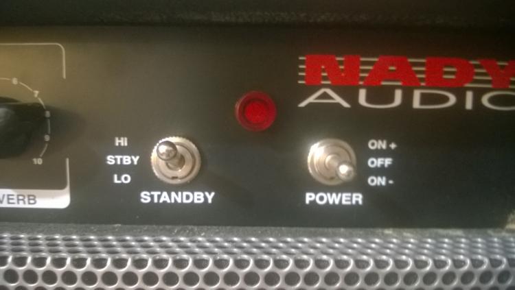
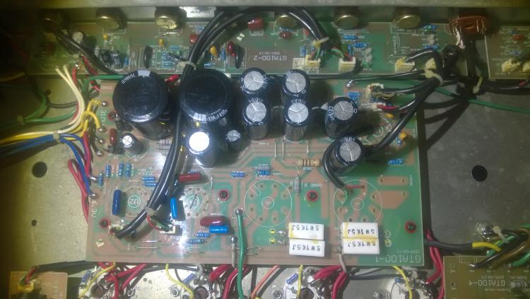
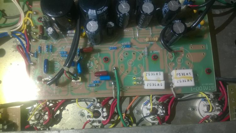
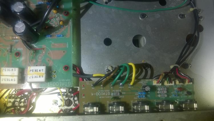
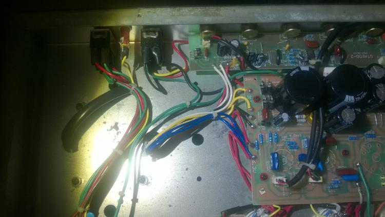
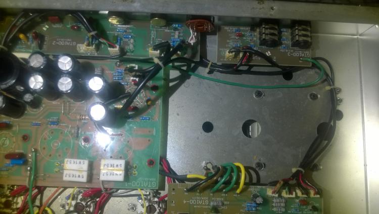
As soon as i get a better camera here ill disassemble the boards and get pics top and bottom.then i'll double check the quality of each pic befor i post anymore.I really want to figure out how the three 12ax7 pre tubes are wired.this thing sound good on setting 1 of the distortion knob but settings 2 and 3 sound horrible.I think on the standby switch for hi and low output settings is done by cutting the output volume of the master volume.from a quick look i would say they just added more resistance to reduce the volume.I thought i would be done buy cutting power to 2 of the output tube but that would make it 50 watts.I plan on making a few mods to cut output in hallf and 1/4 if possible?sorry for the long message,and thank you very very much for your time.