ROG Mr. Eq compact protoboard layout

classic Classic list List threaded Threaded
2 messages Options
Reply | Threaded
Open this post in threaded view
|

ROG Mr. Eq compact protoboard layout

fx-fidden
Hello, this is a little equalizer by ROG, I guess not so famous, but useful anyway, I think.

Here you can find any information about it. http://www.runoffgroove.com/mreq.html

I never built it, but I like the idea to build it and add an easy eq in my DIY 1590A pedal collection.
You can find the original layout in this document http://runoffgroove.com/MrEQ-layouts.pdf.
It's not small enough. So I tried to redesign it.
It's just a bit modified, so it could work, but I signed it still as unverified.


I'm not 100% sure if it fits into a 1590A box. The board is a bit longer, so the input and output jack should be mounted as close as possible to the top of the box, and put the board over it without hinder the board. I never do it, but someone does.

Probably the board should be placed over the three toggle switches, we don't have much alternative. So we should isolated the three switches from the board we place on it.

And the parts on the board have to be more low profile possibile. I advice to use box film caps.
The 220uF could be a problem, the only thing to do is, I guess, to use a 11mm lenght one and bend over. The ground wire could start from any other spot from the ground track.

Another trick to earn a bit of room is to leave off the inner nut of the switches. It will be a bit more out from the box, but maybe I wanted to use the ones with short lever.

I can't build it soon, but let us to know if someone want to try it.
I build pedals
Reply | Threaded
Open this post in threaded view
|

Re: ROG Mr. Eq compact protoboard layout

fx-fidden
This post was updated on .
Ok, I built this circuit, finally. It's almost done and partially verified.

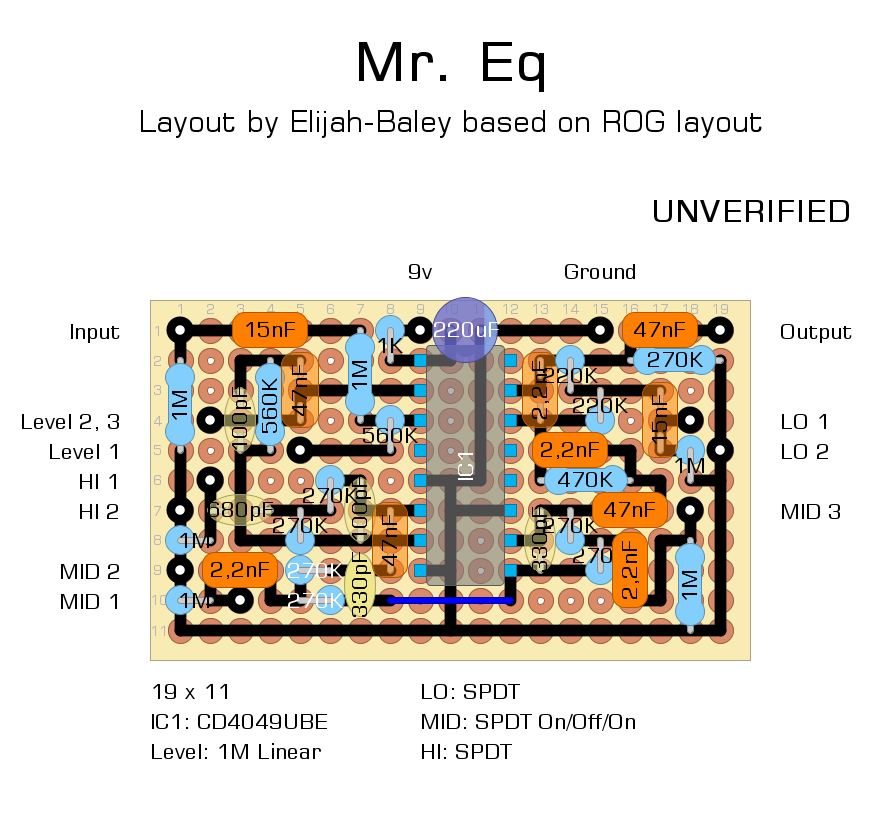
Actually I improved that a bit, so the layout si a bit different.
All the switches are On/Off/On because my intention was to have all the three bands boost/flat/cut.
Mid is already like that. Bass and Treble just boost, but I includede a mode to get a sort of passive cut of the bass and the treble.

That is the new schematic:


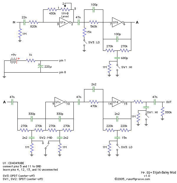
The input cap is a more common 22nF.
I change the gain resistor in front and in the first feedback loop to get less min volume and more max volume.
The last resistor is a 330k, just because I didn't have enough 270k, but that's ok.

It needs a bit of explanation about HI and LO switches.
The HI switch can have just one contact close at the time. The original half one boost treble, the new half part is a low pass filter that cut high end.

The LO switch is a DPDT, it also have one contact close at the time, and it is a compromise.
I'd have preferred to play with caps in parallel or in series to get a bass cut. But I didn't find any wiring using just an half of the DPDT to get: On1 position bass boost, Off position flat (no cut, no boost), On2 position bass cut.
I can use just a DPDT for LO because I want to put this circuit into a 1590A box.
So On1 is the original position that boost the bass. Off position don't connect anything. On2 connect the resistor to the ground and get a high pass filter. Unfortunately, I lose about 0.8db.

If you have some idea to get Boost/Flat/Cut with just half DPDT using caps let me know. I really didn't find any solution.

If someone is interested I'll post the update layout.
I build pedals