Request for Pics - boxing; final wires to circuit

Request for Pics - boxing; final wires to circuit

|
To any one of you talented builders who are really good at getting boxes wired up in a neat & clean fashion - with all wires to the pots and foot switch exactly the right length; I would really like to see that process.
It seems that every "how to" I have seen on the web skips that step. They all go from "first I wire all the grounds together" to "and then I connect my circuit board and I am done." Wait a minute.....! That's like magic to me. The hardest part. One person told us he puts all fresh pots in, checks the wire lengths, then takes them out and wires them to the board (or something like that). Another option would be to mount the pots and lift one side to wire them all to the VERO measuring as you go. Then you would have to unmount them on one side to lift the board the other way and wire the other side. Is it something like that? Just a simple question/answer would help... which order do you wire in; your pots, DC jack, 3.5mms and LED; before or after they are mounted in the box? If before - how do you connect wires to the circuit board? What if you have to troubleshoot - do you unmount everything - because that is the hardest part for me, but it would be a lot easier if I already knew where I wanted things to go before I did my wiring. Maybe the key is knowing when to plan the wiring? Every board I mount is just a B>I>T>C>H.... It looks good once I screw it shut, if it works, but the process is not by any means under my control and it's a hamster cage of wire on the inside. |
|
|
Hey Paul,
I'm not necessarily a talented builder, but I have adopted a process after my first couple of builds were as you described - lots of trial and error! Here is a sample image for a Hao Rust Driver I built (modded with a tone control, hence two pots). 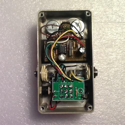 (1) I build my veros with the control wires attached to the board but without the pots soldered. For testing I use alligator clips to attach the pots to wires and my test jig (not elegant but it works). (2) When I'm ready to box, I take my undrilled enclosure and drill out all holes for pots, switches, LED, jacks. I won't go into this, but I take some time with this as I don't want to mess up a good enclosure. TIP: I use 1590Bs for small 1,2 knob circuits, the deeper 125Bs for 3-4 knob circuits, and 1590BBs for large circuits and many knobs (like the Britannia). I REALLY like the extra depth of the 125B as this makes boxing a LOT easier. (I know there are people who have no problem with thinner enclosures like the 1590B.) TIP: Decide upon an enclosure format. That is, where do you want the jacks, 3PDT switch, LED, and pots mounted? If you decide this up front, it saves you a lot of headache. I have adopted the side mounted jacks, 3PDT swictch about 1" from the bottom, LED to the left of the switch, no battery. I drew these layouts out on paper to check all clearances. The jacks locations can be tricky, so keep those in mind when planning. (3) I start boxing by mounting the pots to the enclosure then placing the board where I think it should go and checking all clearances. I even temporarily mount the jacks to check clearances. When I'm happy, I measure the wires and clip them to length. I then remove the board and pots and solder all of the control wires to the pots. All that should remain after that were the +9V, ground, in, and out wires. TIP: If you have to mount your vero to the back side of the pots, think about how to secure the board that won't lead to a short. One thing I have done is to glue a thin piece of plastic board with a dab of gel superglue on the back side of each pot, pots mounted in your box (perfboard from Radio Shack works well for this). Once the glue sets you can remove the board+pots as a unit. Secure the vero circuit board to the perfboard using a mounting of your choice (I use a double-sided mounting tape from the art supply store). You can then solder the wires to pots. If all goes well, you should be able to put the whole unit back in the box as a single component, much like a PCB with board-mounted pots. In the example shown in the picture, the vero was small enough that I could mount it to the enclosure below the pots with foam and double-sided tape. (4) I use a 3PDT board from Vic Audio as shown in the picture. This greatly simplifies the switch, power, board wiring! It even has a place for the LED and LED resistor. You can solder this to the back of your 3PDT switch at any time along with the LED resistor (I use 4.7K ohms). (5) With the board and pots in place in the enclosure, I mount the audio jacks and the 9V jack. I solder wires to the 9V jack before mounting. (6) I mount the LED in its bezel then attach that to the enclosure. (7) I then mount the 3PDT switch with the board. The LED wires can be soldered to the board after the switch is in place. (8) At this point, the only thing left is to solder the vero board wires, 9V jack, and audio jack wires to the 3PDT board (there are places for each on the board - very easy!). That's about it. Again, planning ahead make this process go much more smoothly. Remember that each effect it different: different board sizes, numbers of controls/switches. You have to keep this in mind when deciding which enclosure to use and how the mount the vero board. TIP: One of the biggest constraints you have is the height of the components on your vero board. Those giant PIO caps may look cool but they will come back to bite you when you find you can't screw the back on! TIP: For the lid (inside of the enclosure) I glue a sheet of thin foam to the lid surface to prevent shorts. Foam can also compress if components are brushing up against the inside of the lid. Hope this helps. I'm sure you'll get plenty of other advice. Have fun!  |
Re: Request for Pics - boxing; final wires to circuit
|
|
Thank you Frank, it looks good to me, better than what I am currently doing for sure. I really appreciate it.
I see planning out the box ahead of time is where I have fallen short, because I have been in a hurry to try circuits out and have not really planned even whether they will be boxed, let alone how. So, I tend to build them and just wire in everything (its easier to keep a project going if its already all connected). Pots & switches are my Waterloo, because I tend to pre-wire everything to the circuit board, then if I decide to box it the natural thing is to just try to cram it in there as it is wired - no pre-measuring. I need to go back to using test pots on screw terminal blocks. Another thing you have going right is your foot switch PCB, mine is labeled on the bottom and needs the wires threaded through tiny holes on the underside - very hard to work on when already screwed down. I have just gone back to no PCB and it is actually faster & easier for me. What you say about the 1/4" jacks is also so true - if you don't drill the holes right you might still get everything in, but it can really be a bitch. But the pots and other wires that need to go to the circuit are the things that really get me. So, I am going to try what you say, using test pots when building, and then mounting new pots when boxing, and measuring the wires after the pots are in place. It makes sense, but when you start doing this stuff, how you will box it in the end is rarely one of the things you think about first. I would also like to start using some kind of slip-on connectors for the pots - to make it easy to change one out if I want. It is funny, because there are actually a lot of different ways people do these things. I would add the battery if I could easily, but it is really inconvenient. I see some people put the CLR by the DC input, some by the foot switch, some on the FS PCB. Not a big deal, except that in fact getting that LED wired, shrink-wrapped and seated so it stays in its holder can really be a hassle, especially re-doing it if it pops out. Thanks again. |
Re: Request for Pics - boxing; final wires to circuit
|
|
By the way - I have stocked up on caps, and I found a seller on eBay of nice sized poly caps in hard to find values:
http://www.ebay.com/itm/360624882883?_trksid=p2060778.m2749.l2649&ssPageName=STRK%3AMEBIDX%3AIT Polyester membrane Capacitors 1nF~1UF/63V 240pcs (10 pieces each value) 1 nf 2.2nf 3.3nf 4.7nf 5.6nf 6.8nf 8.2nf 0.01uf 0.015uf 0.022UF 0.033UF 0.047UF 0.056uf 0.068UF 0.082uf 0.1UF 0.15UF 0.22UF 0.33UF 0.47UF 0.56uf 0.680uF 0.82 1 UF TOTAL: 240 pcs $17.99 I also found that if you buy individually you can get much smaller profile electrolytics in larger values. These are very small: http://www.ebay.com/itm/230978304338?_trksid=p2059210.m2749.l2649&ssPageName=STRK%3AMEBIDX%3AIT - 25 for $3.00 with free shipping. |
«
Return to Open Chat
|
1 view|%1 views
| Free forum by Nabble | Edit this page |